
Plasma surface treating method and apparatus therefor

Inactive Publication Date: 2005-06-09
BBK BIO +2
View PDF2 Cites 3 Cited by
  • Summary
  • Abstract
  • Description
  • Claims
  • Application Information

AI Technical Summary

Benefits of technology

[0010] According to the thus configured invention, when, in the state where a magnetic field is formed in the vicinity of the pointed ends of the pair of discharge electrodes, a pulse voltage is applied to the pair of discharge electrodes to produce corona discharge between the pointed ends of the electrodes, excited species including plasma produced by the corona discharge exist in the magnetic field, and the magnetic field applies a pushing force, i.e., a Lorentz force on charged particles in the plasma moving in the magnetic field. Because of the Lorentz force, a force which is perpendicular to the magnetic field is applied to the excited species including plasma. Even when a gas such as high-pressure high-speed air is not ejected, therefore, excited species can be vigorously irradiated toward the workpiece surface in a substantially uniform manner over a wide area. Since a gas such as air which does not directly participate in the surface treatment itself is not used, only excited species which are effective components of the surface treatment are irradiated, so that the loss of excited species due to splash of the gas or the like can be suppressed. Therefore, the surface treatment performance and the treatment efficiency can be remarkably improved.
[0011] In the plasma surface treating method and apparatus of the corona discharge type, as the pulse voltage to be applied to the discharge electrodes, either of a rectangular pulse voltage as set forth in claims 2 and 6, or a pulse voltage formed by plural pulsating waves obtained by half-wave rectifying or full-wave rectifying an alternating voltage as set forth in claims 3 and 7 may be used. In the case where a pulse voltage formed by pulsating waves is used, particularly, a special pulse voltage generating power source is not required, and a pulse voltage of a desired period and duty can be applied by using a simple power source device configured by a combination of an AC power source of the commercial or ultrasonic range and rectifying elements such as diodes. Therefore, reduction of the cost of the apparatus can be realized.
[0012] The magnetic field forming means in the plasma surface treating apparatus of the corona discharge type may be either of means configured by a permanent magnet, a pair of magnetic members, and a pair of pole pieces which form a gap between end faces as set forth in claim 8, or that configured by an electromagnet connected to a DC power source, a pair of magnetic members, and a pair of pole pieces which form a gap between end faces as set forth in claim 9. In the case where a permanent magnet is used, the production cost and the power consumption can be reduced. By contrast, in the case where an electromagnet is used, the production cost and the power consumption are increased as compared with the case where a permanent magnet is used, but a Lorentz force, and therefore the irradiation power and irradiation diffusion range of excited species including plasma can be controlled easily and arbitrarily in accordance with the surface morphology of the workpiece and the like, by adjusting the magnetic flux density in the gap between the end faces of the pole pieces. Therefore, the shape adaptability to the workpiece can be expanded, and the treatment performance and the treatment efficiency can be further improved.

Problems solved by technology

Therefore, the whole apparatus tends to be increased in size and cost.
Although the amount and area of irradiation of excited species can be controlled by adjusting the pressure and angle of the gas ejection, the adjustment range is inevitably restricted.
Particularly, it is difficult to averagely uniformly irradiate the whole workpiece, surface with excited species, in both technical and structural viewpoints.
Since a gas such as air which does not participate in the surface treatment itself is ejected together with excited species to the surface of a workpiece, moreover, the amount of effective excited species is small with respect to the total irradiation amount, and excited species are largely lost due to splash and peripheral escape of the gas such as air, thereby causing a problem in that improvements of the predetermined surface treatment performance and the treatment efficiency are limited.

Method used


Image

  • Plasma surface treating method and apparatus therefor
  • Plasma surface treating method and apparatus therefor
  • Plasma surface treating method and apparatus therefor

Examples


Embodiment Construction

[0022] Hereinafter, embodiments of the invention will be described with reference to the drawings.

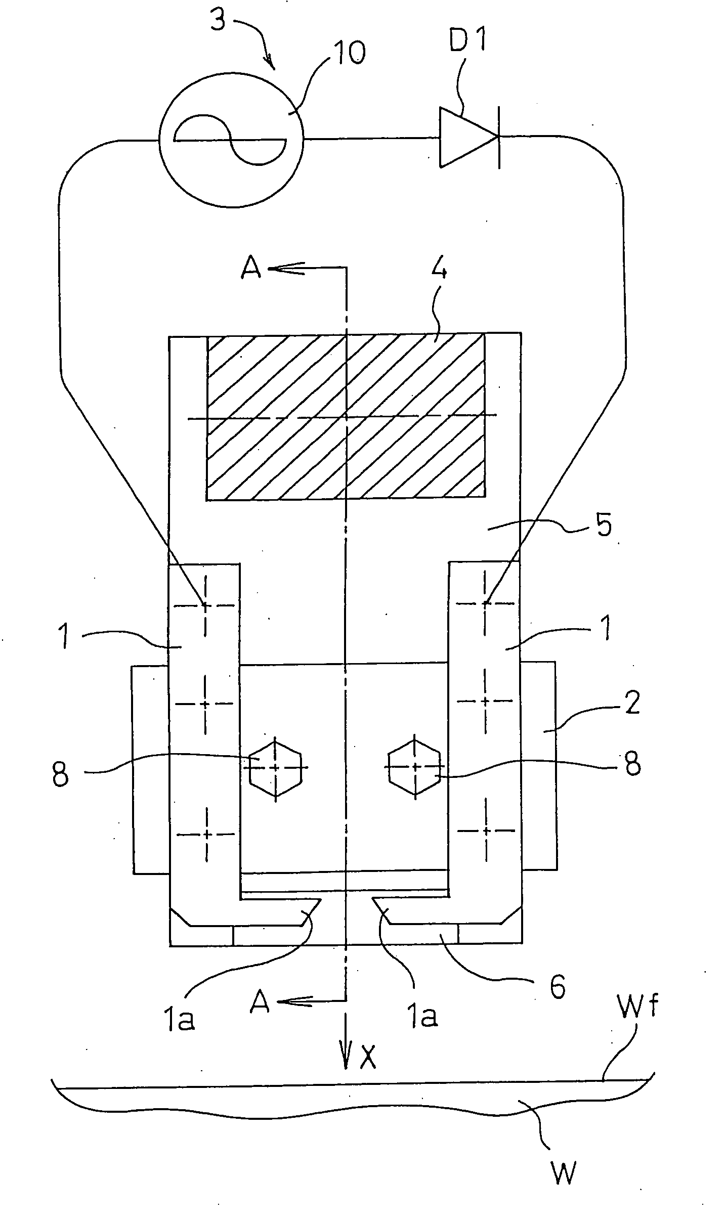
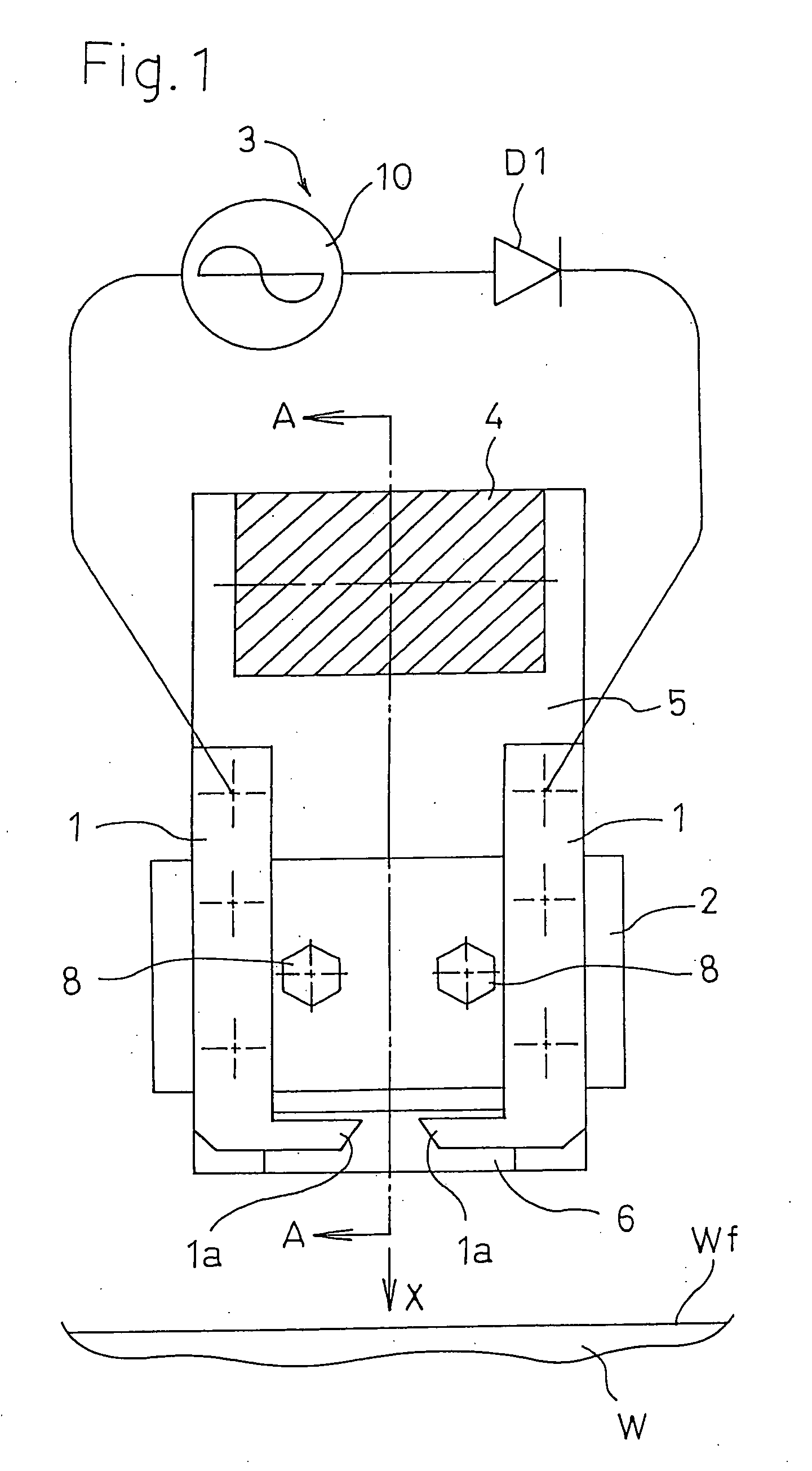
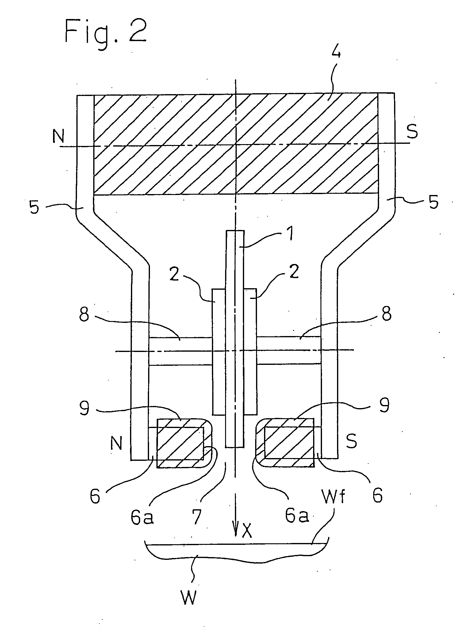
[0023]FIG. 1 is a partially omitted longitudinal front section view showing a first embodiment of the plasma surface treating apparatus of the invention, and FIG. 2 is a longitudinal side section view taken along the line A-A in FIG. 1. The plasma surface treating apparatus of the first embodiment is configured in the following manner. A pair of (+) and (−) discharge electrodes 1, 1 which are produced from a metal material such as stainless steel into an approximately L-like shape are clampingly fixed between electrode holders 2, 2 made of an insulator, in a state where their pointed tip end portions or pointed ends 1a, 1a are opposed to each other. A power source device 3 (described later) which, as a pulse voltage, applies a pulse voltage formed by plural pulsating waves obtained by half-wave rectifying or full-wave rectifying an alternating voltage is connected to the pair of discha...


PUM


Abstract

Without requiring ejection of air or the like, the amount and area of irradiation of excited species to a workpiece surface can be increased, the whole surface can be uniformly irradiated, and the loss of effective excited species can be suppressed, whereby the treatment performance and the treatment efficiency can be remarkably improved. In a method in which a pulse voltage is applied to a pair of opposing discharge electrodes 1, 1 to produce corona discharge between pointed ends 1a, 1a, and excited species including plasma are produced by the corona discharge, thereby conducting a surface treatment, a magnetic field is formed in the vicinity of the pointed ends 1a, 1a of the discharge electrodes 1, 1, by magnetic field forming means configured by a permanent magnet 4, magnetic members 5, and pole pieces 6, and the excited species are irradiated toward the surface Wf of a workpiece W by a Lorentz force which acts as a pushing force on charged particles moving in the magnetic field, thereby conducting a surface treatment.

Description

TECHNICAL FIELD [0001] The present invention is applied mainly to various surface treatments such as those of, in the case where application of a coating composition or a printing process is conducted on a resin such as polyethylene, polypropylene, or PTFE (polytetrafluoroethylene), modifying the water-repellent property of the surface to the water-attracting property, washing away organics adhering to the surface of glass, ceramics, a metal, or a semiconductor, conducting disinfection or sterilization, and performing an etching process. More particularly, the invention relates to a plasma surface treating method of the corona discharge type in which a surface treatment such as modification is conducted by irradiating the surface of a workpiece with excited species such as excited molecules, radicals, or ions which are generated as a result of molecular dissociation due to plasma produced by corona discharge, and also to an apparatus therefor. CONVENTIONAL ART [0002] A plasma surfac...

Claims


Application Information

Patent Timeline
IPC IPC(8): H01J37/32H05H1/24
CPCH05H1/24H01J37/3266H05H1/471
Inventor SAEKI, NOBORU
Owner BBK BIO
Learn More