
Vane pump

a technology of vane pump and manufacturing cost, which is applied in the direction of rotary/oscillating piston pump components, machines/engines, liquid fuel engines, etc., can solve the problems of increasing the number of man-hours and the increase of the manufacturing cost of the apparatus having the vane pump, and achieve the effect of reducing the manufacturing cost of the apparatus

Inactive Publication Date: 2022-06-09
KYB CORP
View PDF2 Cites 0 Cited by
  • Summary
  • Abstract
  • Description
  • Claims
  • Application Information

AI Technical Summary

Benefits of technology

The present invention aims to lower the cost of making an apparatus with a vane pump.

Problems solved by technology

As described above, because steps of assembling and disassembling the anti-detachment member to / from the pump housing are required, the number of man-hours is increased, and as a result, there is a concern that a manufacturing cost of an apparatus having the vane pump is increased.

Method used


Image

  • Vane pump
  • Vane pump
  • Vane pump

Examples


first embodiment

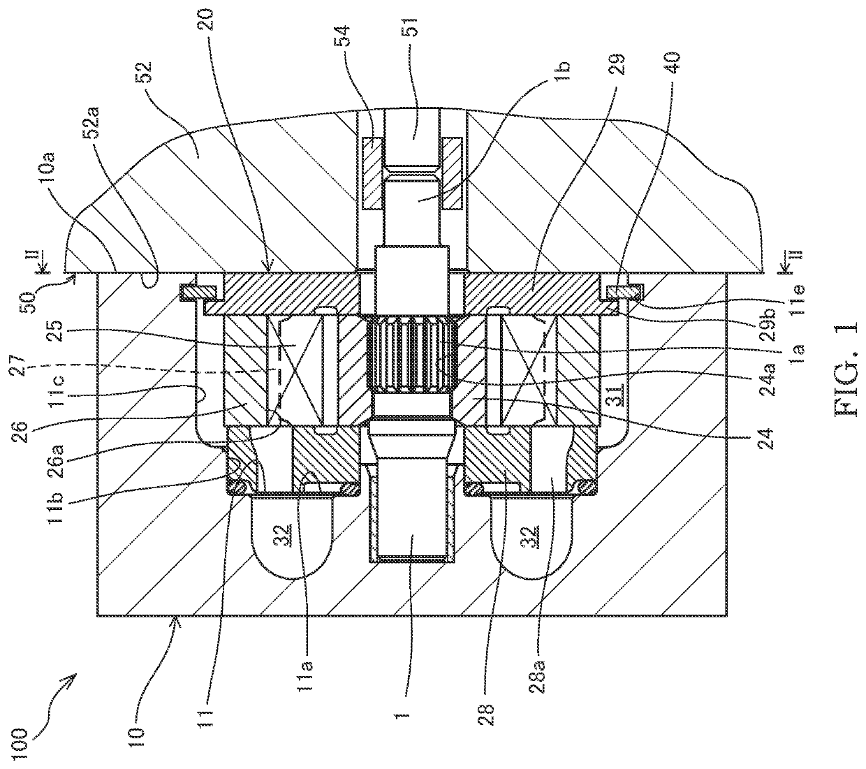
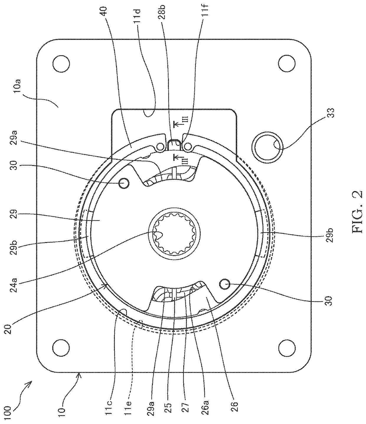
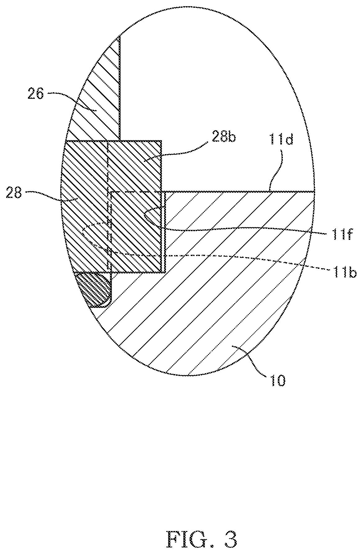
[0015]A vane pump 100 according to a first embodiment of the present invention will be described with reference to FIGS. 1 to 3. FIG. 1 is a sectional view showing a state in which the vane pump 100 according to the first embodiment of the present invention is assembled to a driving source 50, FIG. 2 is a sectional view showing a cross-section taken along a line II-II in FIG. 1, and FIG. 3 is an enlarged sectional view showing a cross-section, in enlargement, taken along a line III-III in FIG. 2.

[0016]The vane pump 100 is used as a fluid pressure source for a fluid hydraulic apparatus, such as, for example, a power steering apparatus, a continuously variable transmission, or the like, mounted on a vehicle. Oil, aqueous alternative fluid of other type, or the like may be used as working fluid. As the driving source 50 for driving the vane pump 100, an engine or an electric motor (not shown) is used.

[0017]As shown in FIGS. 1 and 2, the vane pump 100 is provided with a pump housing 10 ...

second embodiment

[0056]Next, a vane pump 200 according to a second embodiment of the present invention will be described with reference to FIGS. 4 to 6. In the following description, differences from the above-described first embodiment will be mainly described, and components that are the same as those in the vane pump 100 according to the above-described first embodiment are assigned the same reference numerals and descriptions thereof will be omitted. FIG. 4 is a sectional view of the vane pump 200 according to the second embodiment of the present invention, FIG. 5 is a sectional view showing a cross-section taken along a line V-V in FIG. 4, and FIG. 6 is an enlarged sectional view showing a cross-section, in enlargement, taken along a line VI-VI inFIG. 5.

[0057]A basic configuration of the vane pump 200 is similar to that of the vane pump 100 according to the above-described first embodiment. In contrast to the vane pump 100 according to the above-described first embodiment in which the pump cart...


PUM


Abstract

A vane pump is provided with: a pump housing having an accommodating concave portion; and a pump cartridge accommodated in the accommodating concave portion, wherein the pump cartridge has: a rotor; a plurality of vanes received in a plurality of slits formed in the rotor; a cam ring formed with a cam face on an inner circumference of the cam ring; and a first side plate provided at the opposite side from a bottom surface of the accommodating concave portion such that the cam ring is located therebetween, the first side plate has a first projected portion projected radially outward, and the pump cartridge is anchored to the pump housing via the first projected portion.

Description

TECHNICAL FIELD[0001]The present invention relates to a vane pump.BACKGROUND ART[0002]JP2018-80687A discloses a vane pump provided with a pump housing having an accommodating concave portion and a pump cartridge that is accommodated in the accommodating concave portion. The vane pump described in JP2018-80687A is attached to an electric motor that is a driving source.SUMMARY OF INVENTION[0003]In the vane pump described in JP2018-80687A, the pump cartridge is fixed by assembling the pump housing to the electric motor. Therefore, in order to prevent the pump cartridge from being detached from the pump housing until the vane pump is assembled to the electric motor, it is required to assemble an anti-detachment member, such as a cover plate, etc. covering the pump cartridge, to the pump housing.[0004]On the other hand, the anti-detachment member needs to be disassembled from the pump housing when the vane pump is to be assembled to the electric motor. As described above, because steps o...

Claims


Application Information

Patent Timeline
Patent Type & Authority Applications(United States)
IPC IPC(8): F04C15/00F04C18/344F04C2/344
CPCF04C15/0073F04C2230/603F04C2/344F04C18/344F01C21/108F04C2240/805
Inventor KUBO, KOUHEIFUJITA, TOMOYUKIAKATSUKA, KOICHIROMAKI, YOSHIYUKI
Owner KYB CORP
Learn More