
Scalable fish rearing raceway system

Inactive Publication Date: 2005-06-09
KENT SEA TECH
View PDF10 Cites 62 Cited by
  • Summary
  • Abstract
  • Description
  • Claims
  • Application Information

AI Technical Summary

Benefits of technology

[0032] Therefore, the principal object of the present invention is to provide a new and improved scalable fish rearing raceway system and method of making same. More particularly, the present invention relates to a new and improved scalable fish rearing raceway system including a greatly increased fish culture zone, water velocity control means, unique fish harvesting / grading channel component, and integrated water quality monitoring and feeding means which greatly reduces direct labor associated with all aspects of the fish rearing process.
[0035] Briefly, the above and further objects of the present invention are realized by providing a new and improved scalable fish rearing raceway system and method of making same which provides for the largest tank ever used to culture warm water fish at high densities, utilizing an elongated portion to maintain optimal current speed. This larger production unit substantially reduces the direct labor associated with the monitoring, feeding and harvesting of fish on a per fish basis, and requires lower capital costs since it requires fewer components such as monitors, feeders, emergency oxygen diffusers and other equipment per unit of fish produced.
[0037] Continuous removal of dead fish from the raceway is accomplished by means of a sinking fish mortality catcher consisting of a screened ramp at the entrance to the hydrocones which collect both moribund (sunken) and “long” dead (floating) fish. A similar device is mounted at the main drain box on the outside of the raceway to capture floating fish mortality. The continuous removal of dead and dying fish significantly reduces labor costs associated with the frequent manual removal of such fish and reduces the transmittal of infectious diseases by the immediate removal of the dead and dying fish.
[0041] Additionally, the raceway is equipped with feed silos that can dispense feed of several sizes and multiple frequency throughout the day. The number and size of fish present is monitored and graded by an electronic underwater scanning device (using infrared or acoustical technology) coupled to a computer microprocessor which reduces the handling stress associated with the counting, grading and netting of fish.
[0042] The raceway can be stocked with uniform sized fish which are grown to market size as a batch culture. Alternatively, grading bars can periodically separate the larger fish, which are then counted and moved underwater to an adjacent raceway through the common fish transfer channel, and the resulting space restocked with smaller fish. This provides a continuous grading and restocking method which results in less cannibalism and a much greater annual yield (in pounds of fish produced).

Problems solved by technology

More than 60% of our seafood supplies are now imported, resulting in a large annual trade deficit ($6.9 billion).
Often there are few or no environmental laws controlling their discharges which result in environmental degradation and little or no overhead costs associated with complying with environmental laws.
As a result, many U.S. aquaculture products are not competitive with foreign aquaculture products.
These earthen ponds were scalable and required relatively small initial capital expenditures to construct, but required large land masses, were inefficient because of the ratio of square footage and consumptive gallons of water required per unit produced.
Additionally the growing conditions and water quality in these ponds was difficult to monitor and control, harvesting was hit or miss, diseases were common and solid waste products and particulates were difficult to remove.
The process of decay also produces by-products such as nitrogen compounds which adversely affect the water quality within the tank.
The fish sorting required to maintain the sizing restrictions often requires mechanical or physical handling and relocation of the fish resulting in stress and trauma which can adversely affect the mortality, overall health and growth rate of the fish.
This method is often less than efficient and may result in additional stress and physical damage to the fish during harvesting.
Each species of fish prefers a particular rate of speed of water resulting in a sizeable percentage of the tank having a flow rate that will not be suitable for optimal fish habitat.
The current technology is very expensive to build and maintain, and becomes even more labor intensive and costly as the number of tank units increase.
Round tanks are not readily scalable to larger systems because of the inherent problems in flow rate differentials and water mixing (as discussed below).
This has become a significant problem in constructing economically efficient large fish farms.
The extreme number of round tanks required for large-scale fish production is counter-productive as they result in increased operational costs and no construction savings, on a cost-per-pound of fish produced basis.
As effective as round tanks can be for small niche aquatic businesses or research systems, they do not offer the economy-of-scale opportunities necessary in the competitive environment of large-scale commercial aquaculture.
While this novel invention provides for means of removal of many of the gross particulates from the water by means of a trapping section at the bottom of the tank, it does not address the major problem of removal of dead and dying fish on a continuing basis.
Disinfection of a small portion of the water without prompt removal of the source of infection would not prevent the spread of the infection throughout the fish population due to physical contact with the decaying matter.
This system does not provide for means of particulate removal or removal of dead or dying fish.
There is no means of providing for sizing of fish and, additionally, there is no provision for a harvesting channel.
However, as seen previously, there is no provision for removal of dead and dying fish which represents one of the most important potential reservoirs of disease within an aquaculture environment.
Increasing the diameter of these small round tanks reveals inherent design restrictions that prevent efficient usage of the entire interior of the tank for rearing fish due to the centrifugal current differential within the confines of the circular space.
Since increased tank diameter exacerbates the differential in water velocity within the tank, these large round tanks become inefficient in terms of space utilization.
Additionally, the ability to scale them to a larger size would not be cost effective.
Moreover, the space between the numerous tanks is essentially wasted space with respect to fish rearing operations.
A method of culturing fish in a plurality of tanks with each tank comprising a relatively independent growing environment would require enormous capital and labor expenditures per fish produced.
Physically sorting and moving the fish from tank to tank would result in a great deal of trauma and possibly injury to the fish.
There is no means provided for removal of heavy particulates, dead or dying fish or providing for circulation of water through the tank.
The fact that these multiple habitats are individually removable suggests that the size of the baskets are relatively small and that the number of units of fish per basket is severely limited.
This ratio of capital expenditure (and labor costs) per unit produced is extremely high.
Additionally, the trauma involved in physical separation of the fish by size into each basket would be very high.
Additionally, there is no means provided for removal of dead or dying fish on a continuous basis, so the likelihood of spread of disease from the presence of dead or dying fish would seem to be overwhelming.

Method used


Image

  • Scalable fish rearing raceway system
  • Scalable fish rearing raceway system
  • Scalable fish rearing raceway system

Examples


Embodiment Construction

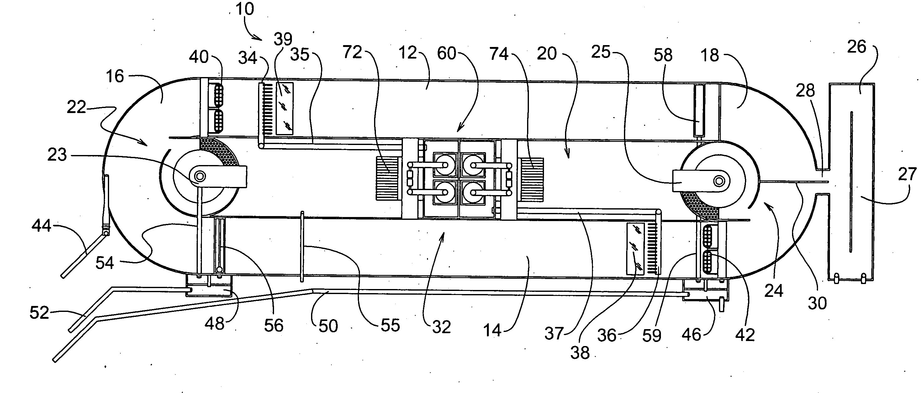
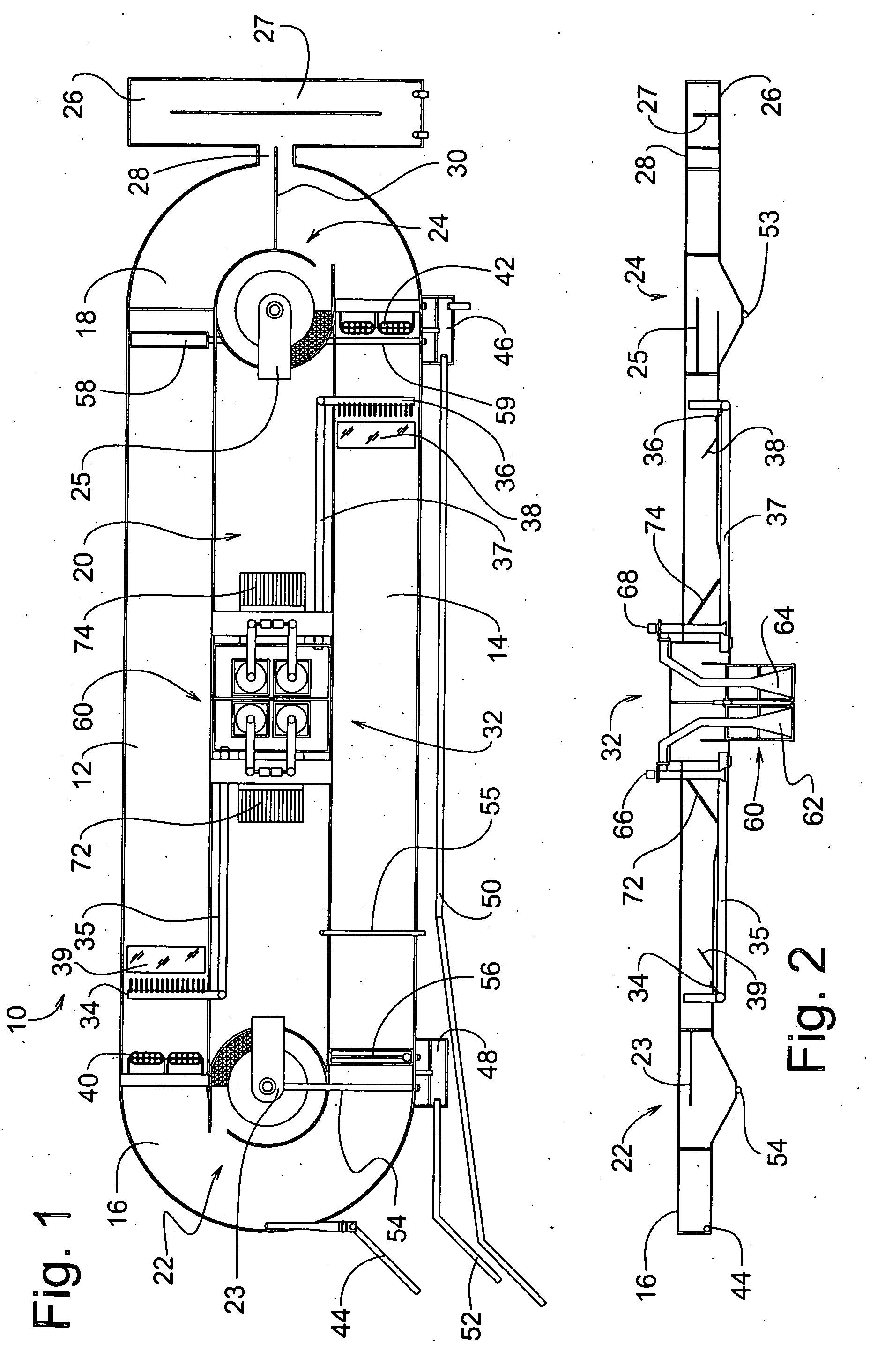
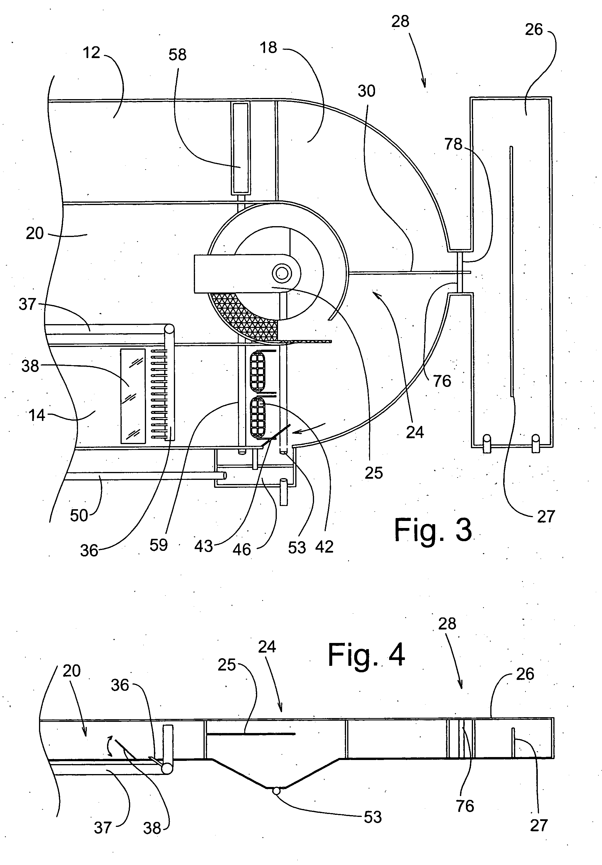
[0058] Referring now to the drawings, and more particularly to FIG. 1 thereof, there is shown a new fish rearing system 10 which consists of two elongated parallel fish channel raceways 12 and 14 and two semi-circular end sections 16 and 18 which are located at either end of the elongated fish channel raceways 12 and 14.

[0059] The new fish rearing system 10 also incorporates an inner water treatment zone 20 where a secondary detritivore fish species, such as tilapia or carp, may be stocked to remove particulate matter. Two hydrocone structures 22 and 24 are located at either end of this inner water treatment zone 20. The hydrocone structures 22 and 24 are provided with overflow trays 23 and 25. The overflow trays 23 and 25 direct the water from the top of the hydrocone structures 22 and 24 to the inner water treatment zone 20.

[0060] A harvesting / grading channel 26 is located at one end of the fish rearing system 10. A partition wall 27 is located along a portion of the midline of ...


PUM


Abstract

A scalable fish rearing raceway system is provided, incorporating a fish containment structure having two semi-circular end sections, and two or more parallel fish raceways, surrounding a central zone for housing water treatment systems and a secondary fish crop. Heavy particulates are eliminated from the main fish rearing channels by use of conical areas located at either end of the parallel elongated raceways. Continuous removal of dead or dying fish from the raceway is accomplished by means of a floating mortality catcher consisting of a screened ramp at the surface of the cones which continuously collect moribund and dead fish. Grading bars separate and move fish underwater to an adjacent raceway through a common fish transfer channel. This larger scalable fish production system substantially reduces the direct labor and capital costs associated with the production of fish as compared with conventional circular fish rearing tanks. Continuous removal of dead fish from the raceway is accomplished by means of a sinking fish mortality catcher consisting of a screened ramp at the entrance to the hydrocones which collect both moribund (sunken) and “long” dead (floating) fish. A similar device is mounted at the main drain box on the outside of the raceway to capture dead and floating fish. The continuous removal of dead and dying fish significantly reduces labor costs associated with the frequent manual removal of such fish and reduces the transmittal of infectious diseases by the immediate removal of the dead and dying fish.

Description

BACKGROUND OF THE INVENTION [0001] 1. Field of the Invention [0002] The present invention relates to a scalable fish rearing raceway system and method of making same. More particularly, the present invention relates to a new and improved scalable fish rearing raceway system including a greatly increased fish culture zone, unique fish harvesting / grading channel component, and integrated monitoring and feeding means which greatly reduces direct labor associated with all aspects of the fish rearing process. [0003] 2. Description of the Related Art [0004] As health conscious Americans begin to consume more fish products and the naturally occurring sources of fish become depleted, there is a growing need to fill the demand for fish products by turning to aquaculture. Aquaculture is defined as the production and husbandry of aquatic plants and animals in controlled environments. The term husbandry means the application of scientific principles to farming. Controlled environments are direc...

Claims


Application Information

Patent Timeline
IPC IPC(8): A01K61/00A01K63/00A01K63/04
CPCA01K61/001A01K63/04A01K63/00A01K61/90A01K61/13A01K61/85A01K61/95A01K63/10
Inventor MASSINGILL, MICHAEL J.CHAMBERLAIN, RODNEY J.CARLBERG, JAMES M.VAN OLST, JON C.
Owner KENT SEA TECH
Learn More