
Functionally improved battery and method of making same

a battery and functional technology, applied in the field of functionally improved batteries, can solve the problems of low electrical energy generation vs. their potential chemical energy ratio, ineffective battery, limited polymer effectiveness, etc., and achieve the effect of increasing the useful life and power outpu

Inactive Publication Date: 2005-06-02
POWER PAPER
View PDF11 Cites 29 Cited by
  • Summary
  • Abstract
  • Description
  • Claims
  • Application Information

AI Technical Summary

Benefits of technology

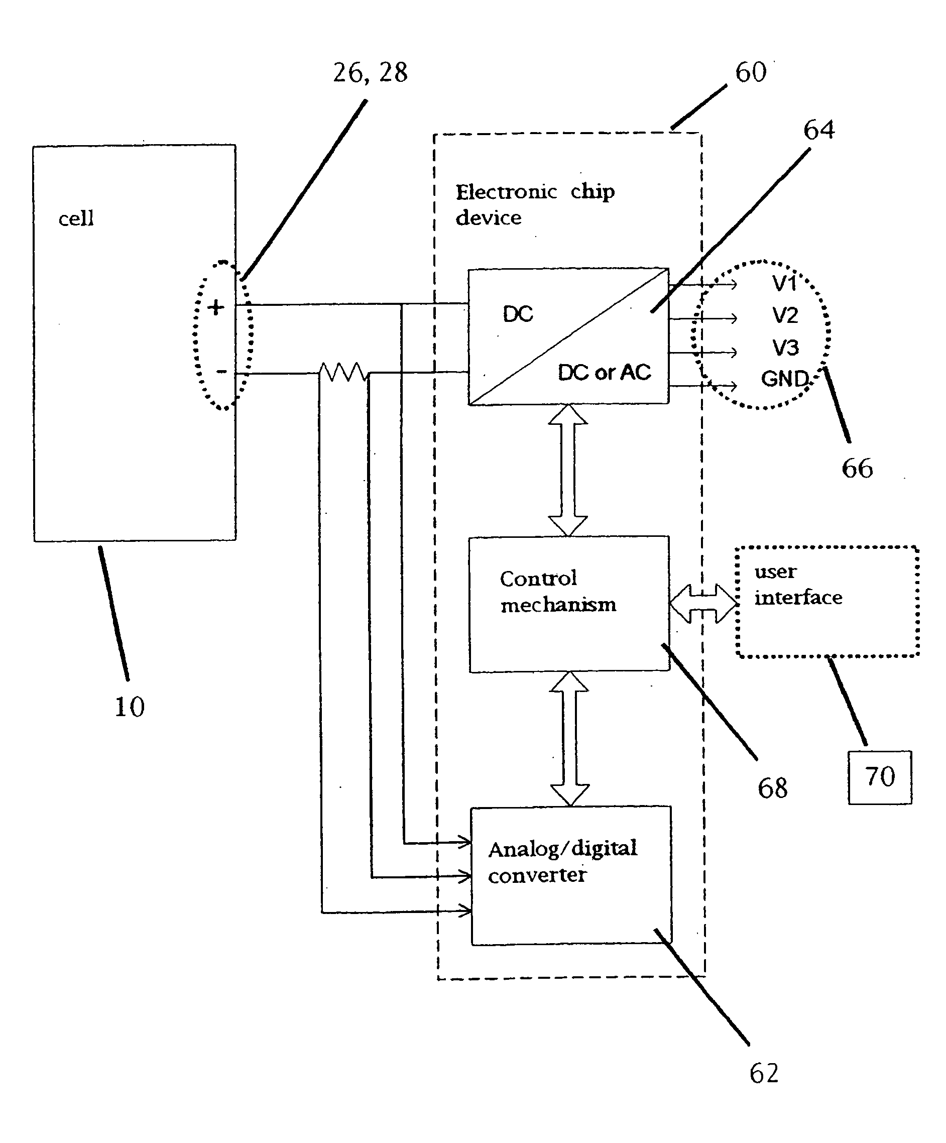
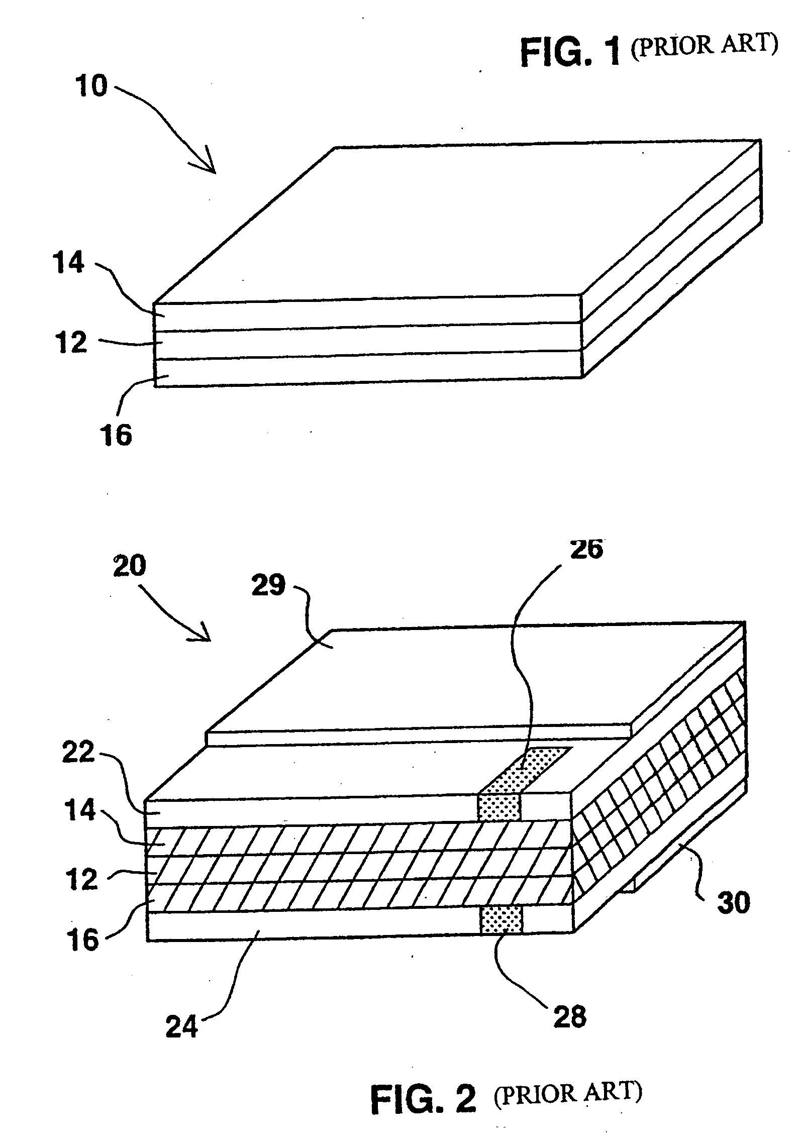
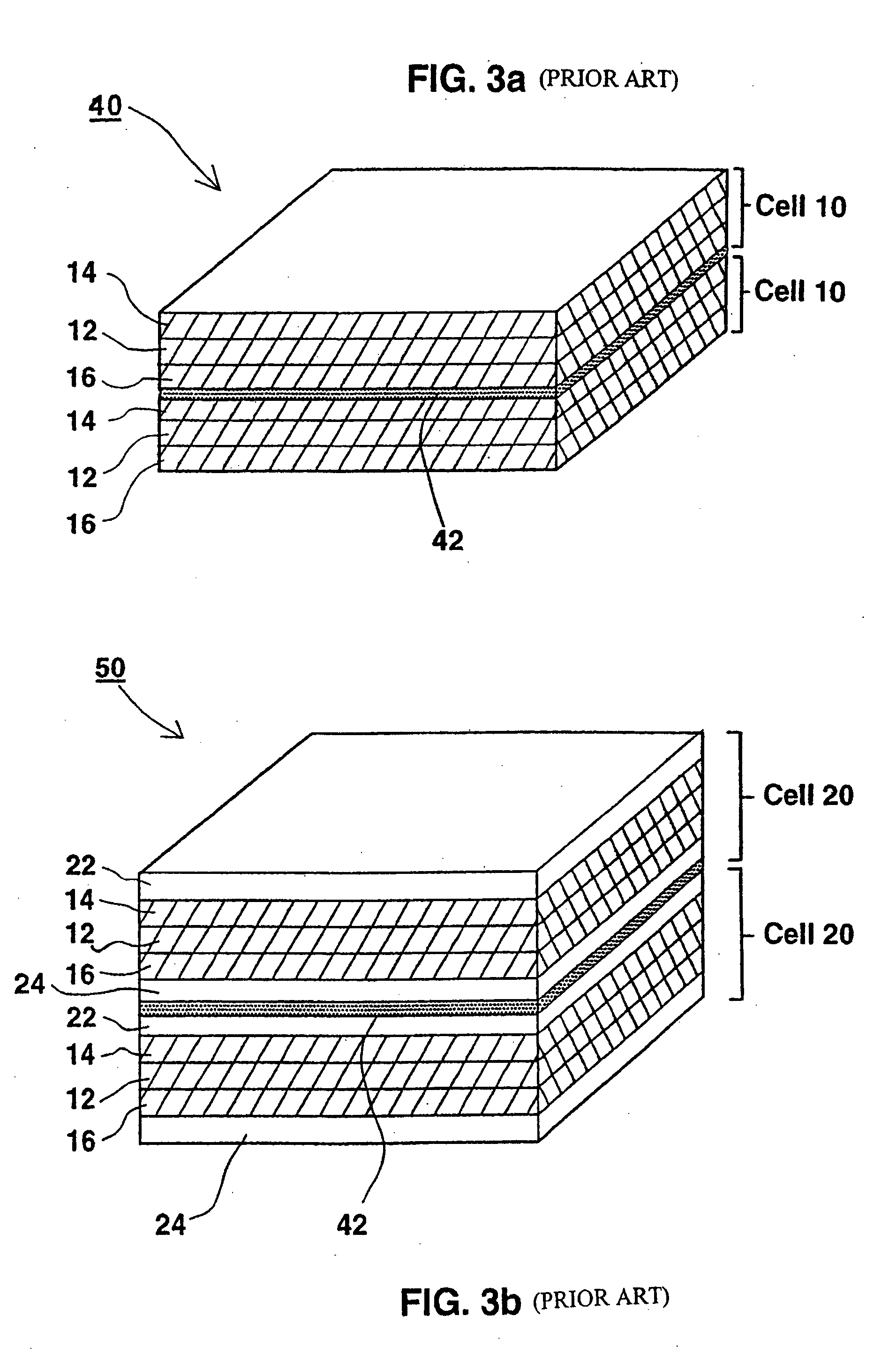
[0014] According to one aspect of the present invention there is provided a functionally improved battery comprising. The battery comprises a flexible thin layer open liquid state electrochemical cell and an electronic chip device. The cell includes a first layer of insoluble negative pole, a second layer of insoluble positive pole and a third layer of aqueous electrolyte. The third layer being is disposed between the first and second layers. The third layer includes (i) a deliquescent material for keeping the open cell wet at all times; (ii) an electroactive soluble material for obtaining required ionic conductivity; and (iii) a water-soluble polymer for obtaining a required viscosity for adhering the first and second layers to the third layer. The electronic chip device is integrally formed on or within the electrochemical cell and serves to improve a functionality of the battery.
[0015] According to another aspect of the present invention there is provided a method of making a functionally improved battery. The method comprises the steps of producing a flexible thin layer open liquid state electrochemical cell and applying thereupon or therein an electronic chip device to improve a functionality of the battery. Production of the electrochemical cell is accomplished by (i) wetting a porous substance having a first side and a second side with an aqueous solution containing a deliquescent material, an electroactive soluble material and a water-soluble polymer; (ii) applying onto the first side a layer of negative pole; and (iii) applying onto the second side a layer of positive pole.
[0032] According to still further features in the described preferred embodiments, wherein the terminals are made of graphite. According to still further features in the described preferred embodiments, the battery further comprises at least one conductive layer improving the electronic conductivity of at least one of the first and second pole layers.
[0051] The present invention successfully addresses the shortcomings of the presently known configurations by providing a battery with an increased useful life and a power output which is more nearly constant over a prolonged service. The present invention further provides a battery which has a selectable power output.

Problems solved by technology

Although solid state batteries have an inherent advantage, they do not dry out and do not leak, they suffer major disadvantages when compared with liquid state batteries since, due to limited diffusion rates of ions through a solid, their operation is temperature dependent to a much larger extent, and many operate well only under elevated temperatures; and, the limited diffusion rates thus described, characterize solid state batteries with low ratio of electrical energy generated vs. their potential chemical energy.
Being closed cells, these batteries tend to swell upon storage due to evolution of gases which is a fatal problem in thin layer batteries having no mechanical support, the pressure imposed by the accumulated gases leads to layer separation, thus turning the battery inoperative.
However, the polymer is limited in its effectiveness and the mercury is environmentally hazardous.
A disadvantage shared by all battery types is that use of the battery after the voltage of the cell(s) drops below the minimum required level for the device operated thereby is infeasible.
The process is technically complex, requires the use of welding ultrasound welding devices, and the input materials are expensive.
As a result, the welding option is commercially unattractive with respect to battery manufacture.

Method used


Image

  • Functionally improved battery and method of making same
  • Functionally improved battery and method of making same
  • Functionally improved battery and method of making same

Examples


Embodiment Construction

[0061] The present invention is of a functionally improved battery which includes a flexible thin layer open electrochemical cell which can be used as a primary or rechargeable power supply for various miniaturized and portable electrically powered devices of, for example, compact design, short use and / or disposable nature. The flexible thin layer open electrochemical cell of the present invention includes a wet electrolyte, yet maintains a flexible, thin and open configuration, thus is devoid of accumulation of gases upon storage. In addition it is equipped with an integral electronic chip device which improves its functionality during service and / or prolongs the batteries lifetime.

[0062] The principles and operation of a flexible thin layer open electrochemical cell employed as part of the present invention may be better understood with reference to the drawings and accompanying descriptions.

[0063] Before explaining at least one embodiment of the invention in detail, it is to be...


PUM

PropertyMeasurementUnit
flexibleaaaaaaaaaa
ionic conductivityaaaaaaaaaa
viscosityaaaaaaaaaa

Abstract

A functionally improved battery is disclosed. The battery includes a flexible thin layer open liquid state electrochemical cell and an electronic chip device integrally formed on or within the electrochemical cell. The cell includes a first layer of insoluble negative pole, a second layer of insoluble positive pole and a third layer of aqueous electrolyte. The third layer is disposed between the first and second layers. The third layer includes and includes a deliquescent material for keeping the cell wet, an electroactive soluble material for ionic conductivity and a watersoluble polymer for viscosity. The viscosity adheres the first and second layer to the third layer. The chip serves to improves a functionality of the battery.

Description

FIELD AND BACKGROUND OF THE INVENTION [0001] The present invention relates to a functionally improved battery and, more particularly, to a battery which includes a flexible thin layer open liquid state electrochemical cell and an electronic chip device integrally formed on or within the battery, which chip improves a functionality of the battery. The present invention further relates to a method of making a functionally improved battery. Specifically, the functional improvements of the batteries of the present invention increase the useful life (service) of the battery and make the battery a more reliable power source. By reliability, as used herein, is meant that a power output from the battery is less prone to undesired changes over time than a prior art battery. [0002] The ever-growing development of miniaturized and portable electrically powered devices of compact design such as, for example, cellular telephones, voice recording and playing devices, watches, motion and still cam...

Claims


Application Information

Patent Timeline
Patent Type & Authority Applications(United States)
IPC IPC(8): H01L23/58H01M4/62H01M6/06H01M6/12H01M6/40H01M6/42H01M6/48H01M10/04H01M10/42H01M10/48
CPCH01L23/58Y10T29/49115H01M6/06H01M6/12H01M6/40H01M6/42H01M6/48H01M10/0436H01M10/4257H01M10/48H01M2300/0002H01M2300/0085H01L2924/0002H01M4/621H01L2924/00Y02E60/10Y02P70/50
Inventor LEVANON, BARUCH
Owner POWER PAPER
Learn More