Disk brake devices
a technology of brake device and disc, which is applied in the direction of noise/vibration control, slack adjuster, brake elements, etc., can solve the problems of large friction force generated between the pad and the mount, and the pad cannot move smoothly in the axial direction, so as to facilitate the pivoting movement, reduce rigidity, and facilitate the effect of movemen
- Summary
- Abstract
- Description
- Claims
- Application Information
AI Technical Summary
Benefits of technology
Problems solved by technology
Method used
Image
Examples
first representative embodiment
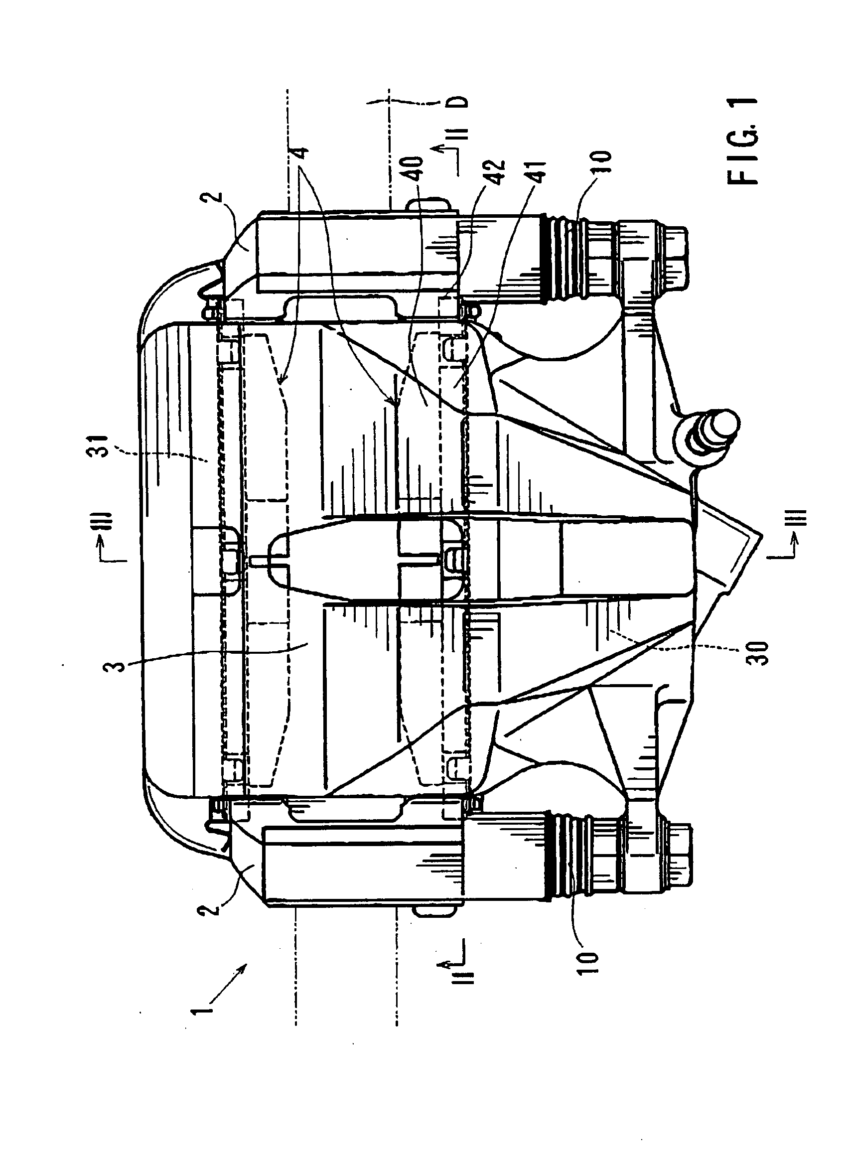
[0057] A first representative embodiment of the present invention will now be described with reference to FIGS. 1 to 3. As shown in FIG. 1, a brake device 1 according to the first representative embodiment generally includes a pair of pads 4, a mount 2, and a caliper 3. The mount 2 is adapted to be attached to a vehicle, such as an automobile (not shown). The pads 4 are supported on the mount 2 and positioned opposing an inner side surface and an outer side surface of the brake disk D (hereinafter simply called “inner side” and “outer side”) The terms “inner side” and “outer side” are determined relative to the vehicle (i.e., the side nearest to the exterior of the vehicle is the “outer sided”).
[0058] The caliper 3 is mounted on the mount 2 via slide pins 10 that are slidably movable relative to the mount 2. Consequently, the caliper 3 is movable relative to the mount 2 in an axial direction of the brake disk D via the slide pins 10. As a result, the brake disk D is typically cente...
second representative embodiment
[0074] A second representative embodiment will now be described with reference to FIGS. 4 through 8. The second representative embodiment is a modification of the first representative embodiment. Therefore, in FIGS. 4 to 8, like members are given the same reference numerals as FIGS. 1 to 3. The description of these members will not be repeated.
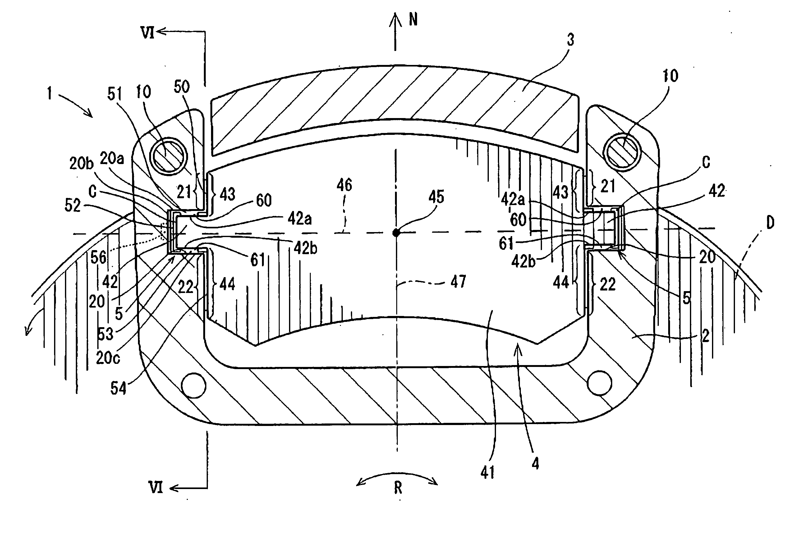
[0075] In this second representative embodiment, as shown in FIG. 4, support members 5 are fitted into the clearances C that are formed between the guide portions 42 of the pads 4 and the support portions 20 of the mount 2. The support member 5 serves to prevent the guide portions 42 and the support portions 20 from directly contacting one another. In addition, the support member 5 aids in preventing the wear and grinding together of the guide portions 42 and the support portions 20.
[0076] Referring to FIG. 5, each of the support members 5 is made of a spring plate. The support members 5 have an integral structure with a pair of pressure rec...
third representative embodiment
[0092] A third representative embodiment will now be described with reference to FIG. 9. The third representative embodiment is a modification of the second representative embodiment. Therefore, in FIG. 9, like members are given the same reference numerals as in FIGS. 4 to 8. The description of these members will not be repeated.
[0093] The third representative embodiment is different from the second representative embodiment mainly in the use of separate resilient members 90 and 91, configured for example as coil springs, in place of support member 5. The resilient members 90 and 91 are disposed within the clearance C formed between the guide portion 42 and the corresponding support portion 20.
[0094] The resilient member 90 is interposed between the radially outward side surface 20a of the support portion 20 and the radially outward guide surface 42a of the guide portion 42. The resilient member 90 is deformed or compressed in order to fit within the clearance C. Therefore, the re...
PUM
 Abstract
Description
Claims
Application Information
 - R&D
- Intellectual Property
- Life Sciences
- Materials
- Tech Scout
- Unparalleled Data Quality
- Higher Quality Content
- 60% Fewer Hallucinations
Browse by: Latest US Patents, China's latest patents, Technical Efficacy Thesaurus, Application Domain, Technology Topic, Popular Technical Reports.
© 2025 PatSnap. All rights reserved.Legal|Privacy policy|Modern Slavery Act Transparency Statement|Sitemap|About US| Contact US: help@patsnap.com


