
Fuel reformer catalyst and absorbent materials

a fuel reformer and catalyst technology, applied in the field of particle materials, can solve the problems of high efficiency of the pox reactor, severe operating conditions, and high cost, and achieve the effect of enhancing the reforming of carbon-based fuel

Inactive Publication Date: 2005-05-26
CABOT CORP
View PDF17 Cites 76 Cited by
  • Summary
  • Abstract
  • Description
  • Claims
  • Application Information

AI Technical Summary

Benefits of technology

[0029] According to another embodiment, a method for absorption enhanced reforming of a carbon-based fuel is provided. The method includes providing a carbon-based fuel, contacting the fuel with at least a first conversion catalyst to catalyze the formation of hydrogen and with a pelletized absorbent compound having a first bulk density, wherein the pelletized absorbent is converted to a carbonized absorbent having a second bulk density and regenerating the carbonized absorbent to form a regenerated absorbent having a third bulk density, wherein the third bulk density is greater than the first bulk density.

Problems solved by technology

These fuel-processing technologies involve multiple steps and severe operating conditions.
The efficiency of the POX reactor is relatively high, however, POX systems are typically less energy efficient than SMR because of the utilization of higher temperatures and the problem of heat recovery.
However, the cost of constructing the distribution infrastructure to safely transport pure H2 gas over large distances presents an economic barrier to the exploitation of fuel cells, particularly for the transportation sector.
However, conventional fuel-processing technologies for H2 production from hydrocarbons are unsatisfactory for providing H2 to PEM fuel cells due to low reforming efficiencies resulting from the multiple steps that are required and the severe operating conditions that are required, as is discussed above.
The low H2 content in the reformate reduces the fuel cell performance and requires that greater amounts of expensive Pt and PtRu catalysts and membrane materials be utilized for reasonable system efficiency as compared to fuel cells operating on pure H2.
The high levels of CO2 in the reformate also cause two additional problems.
Also, the acidic nature of CO2 and water solutions promotes a number of reactions that can reduce the useful lifetime of the PEM stacks by greater than 50%.
PSA requires operation at a significant pressure, which lowers system efficiency and produces a tail gas containing 25% to 30% of the H2 produced during column blowdown and purge.
The CO2 absorbents typically used for AER have poor reactivity, low CO2 capacity, and poor recyclability.
The capture of CO2 accounts for about 75% of the total cost of CO2 management, and imposes a severe energy requirement on fossil fuel-based power plants, reducing their net electricity output by as much as 37%.
However, this practice reduces the overall efficiency of the power generation plant significantly.
While various absorbents have been proposed for desulfurizing hot coal gas, few are effective at such high temperatures.
Natural CaO-based absorbents such as limestone and dolomite are plentiful and inexpensive, but they are soft and friable and do not stand up well to handling and recycle use.
The foregoing methods generally result in limited control over the composition and microstructure of the powders.

Method used


Image

  • Fuel reformer catalyst and absorbent materials
  • Fuel reformer catalyst and absorbent materials
  • Fuel reformer catalyst and absorbent materials

Examples


examples

[0235] The following examples illustrate the production and application of the AER materials according to the present invention, including absorbents, SMR catalysts and multi-functional composite materials.

Absorbents

[0236] The absorbent materials according to the present invention can be fabricated by spray-pyrolysis or spray drying, and either fabrication method can be followed by post-processing. The following specific examples illustrate some of these embodiments.

example a-1

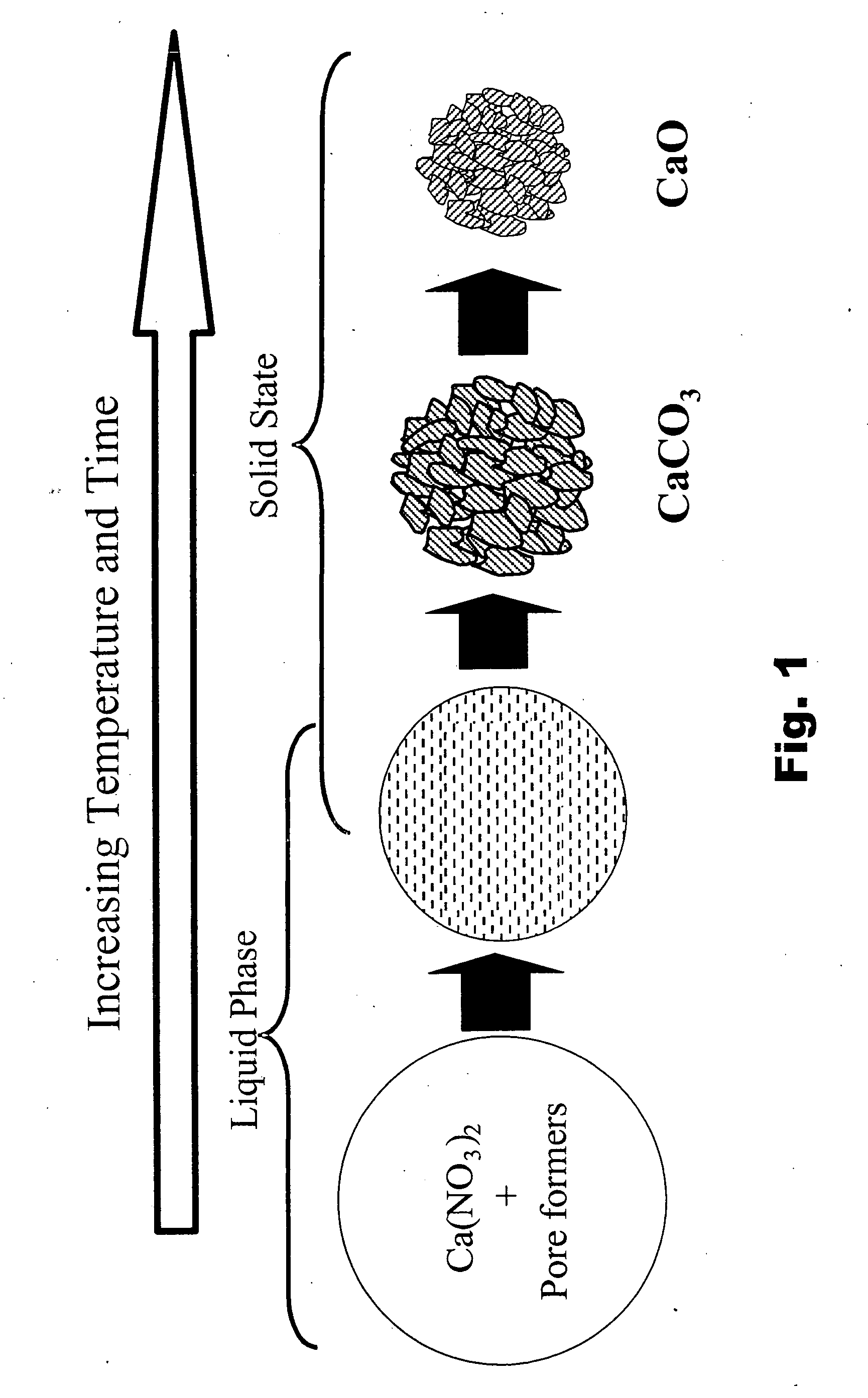
[0237] This example illustrates the production of a 5 g batch of Ca-oxide (CaO) absorbent according to the present invention by spray pyrolysis. 21 g of Ca-nitrate (Ca(NO3)2) is dissolved in 178 g of de-ionized water. 1 g of lactic acid and 1 g of NH4-nitrate (NH4NO3) is added while stirring and the solution is stirred for 10 minutes. Spray pyrolysis is conducted on an ultrasonic transducer system at a furnace temperature of 900° C., with air as both the carrier gas and the quench gas at 60 SLPM and 5 SCFM, respectively. The reaction residence time of the system is 1.5 seconds, as calculated by the quotient of the system volume and the carrier gas flow rate corrected for temperature expansion. The collected powder batch consists essentially of CaO.

example a-2

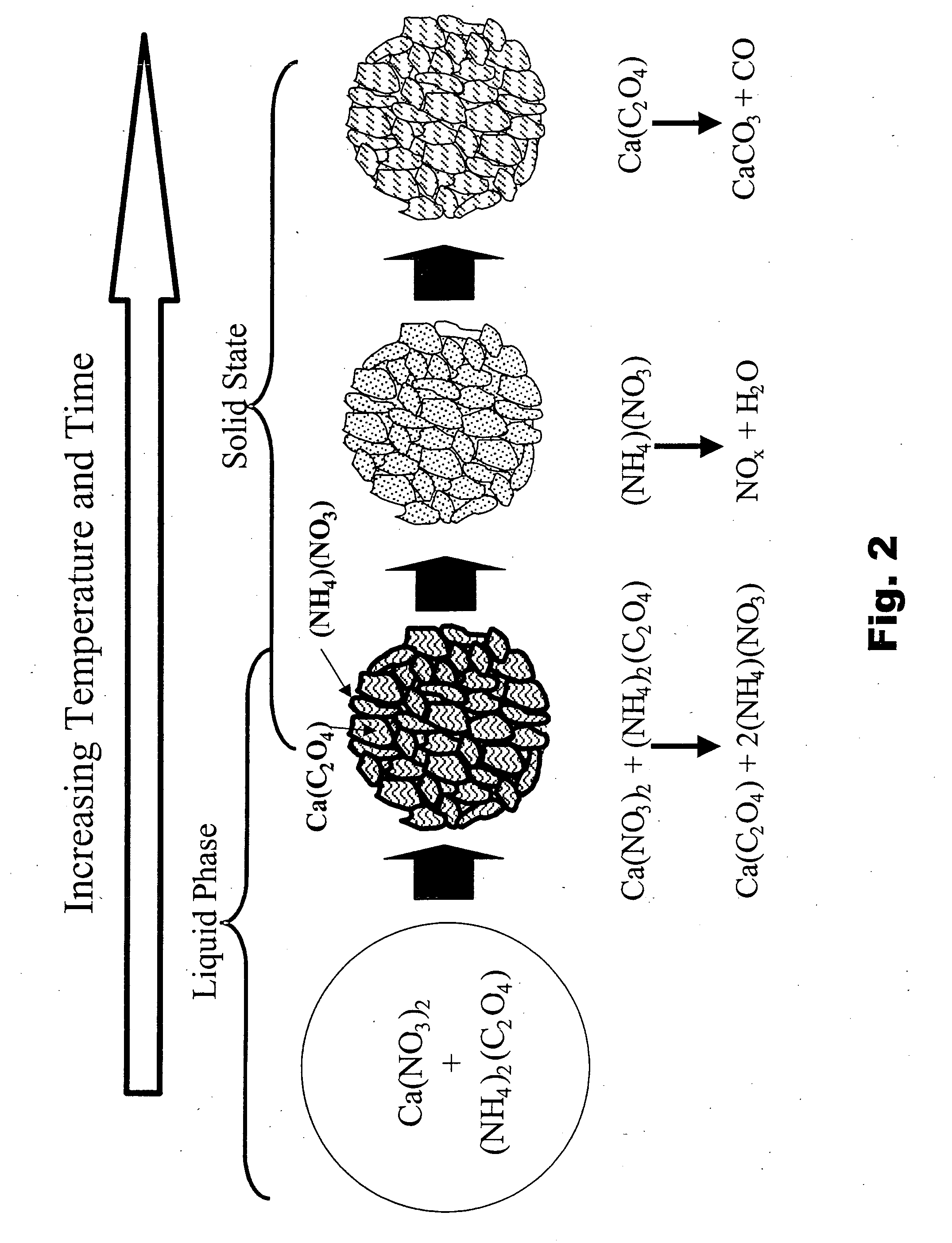
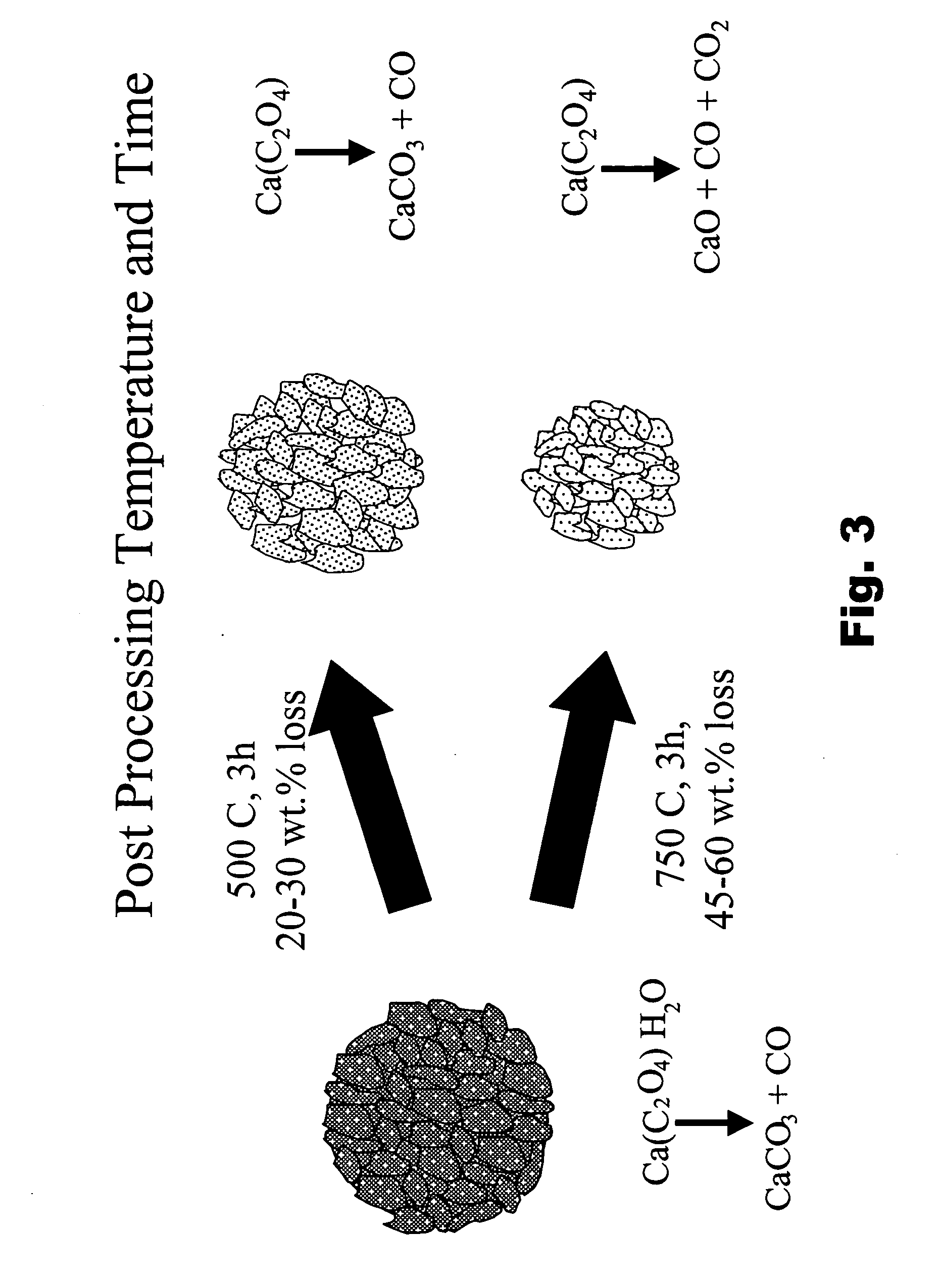
[0238] This example illustrates the fabrication of a 1 kg batch of Ca-oxalate (CaC2O4) according to the present invention using a spray dryer. 1.84 kg of Ca-nitrate is dissolved in 2 kg of de-ionized water and 1.11 kg of NH4-oxalate is dissolved in. 4.5 kg of de-ionized water. The two solutions are individually mixed on shear mixers for 30 minutes. The Ca-nitrate solution is slowly added to the NH4-oxalate solution while shearing. The resulting ˜10 wt. % solids dispersion of precipitated Ca-oxalate is sheared for an additional hour. The precursor dispersion is fed into a mixed-flow spray dryer at a liquid feed rate to maintain inlet / outlet temperatures of 975° F. / 580° F. (524° C. / 304° C.), using a two-fluid nozzle with an air pressure of 65 psig. The residence time of the system is 10 seconds as calculated by the quotient of the system volume and the gas flow rate corrected for expansion using the outlet temperature. The powder is collected using a cyclone. The powder batch consists...


PUM

PropertyMeasurementUnit
temperatureaaaaaaaaaa
total massaaaaaaaaaa

Abstract

Materials that are useful for absorption enhanced reforming (AER) of a fuel, including absorbent materials and catalyst materials. The materials can be fabricated by spray processing. The use of the materials in AER can produce a H2 product gas having a high H2 content and a low level of carbon oxides.

Description

CROSS-REFERENCE TO RELATED APPLICATIONS [0001] This application is related to U.S. Provisional Patent Application Serial No. ______ by Hampden-Smith et al., entitled CARBON DIOXIDE ABSORBENT MATERIALS AND METHODS FOR MAKING SAME, and filed on Nov. 26, 2003, the disclosure of which is incorporated herein by reference in its entirety.BACKGROUND OF THE INVENTION [0002] 1. Field of the Invention [0003] The present invention relates to particulate materials that are useful for fuel reformers, such as catalyst materials for hydrogen production from carbon-based fuels and absorbent materials for the removal of acid gases such as CO2 and H2S from gas streams. The particulate materials can be produced by spray processing of precursors to form a powder batch. The present invention is also directed to fuel reformers incorporating the particulate materials and methods for using the materials. The present invention is also directed to the combination of a highly reversible, high-capacity CO2 abs...

Claims


Application Information

Patent Timeline
Patent Type & Authority Applications(United States)
IPC IPC(8): B01J20/04B01J23/46B01J23/58B01J35/10B01J37/00B01J37/08C01B3/38C01B3/56
CPCB01J20/041B01J20/28019B01J23/58B01J35/1019B01J35/1038B01J35/1061B01J37/0045B01J37/086C01B3/38C01B3/382C01B3/386C01B3/56C01B2203/0227C01B2203/0233C01B2203/0261C01B2203/042C01B2203/0425C01B2203/0475C01B2203/1241C01B2203/1247B01J20/08B01J20/3433B01J20/3483B01J23/464Y02P20/52B01J35/633B01J35/647B01J35/615
Inventor HAMPDEN-SMITH, MARK J.ATANASSOVA, PAOLINASHEN, JIAN-PINGNAPOLITANO, PAULBREWSTER, JAMES
Owner CABOT CORP
Learn More