
Chromatic dispersion compensator (CDC) in a photonic integrated circuit (PIC) chip and method of operation

a technology of photonic integrated circuit and compensator, which is applied in the field of wdm or dwdm systems, can solve the problems of high manufacturing and implementation cost, and achieve the effect of more effective functionality

Inactive Publication Date: 2005-05-26
INFINERA CORP
View PDF30 Cites 42 Cited by
  • Summary
  • Abstract
  • Description
  • Claims
  • Application Information

AI Technical Summary

Benefits of technology

The invention is about an optical equalizer / chromatic dispersion compensator (E / CDC) that can correct the equalization and chromatic dispersion of multiplexed channel signals in a single device. The E / CDC includes an input / output for receiving the multiplexed channel signal, an optical amplifier, a variable optical attenuator, and a chromatic dispersion compensator. The CDC separates the multiplexed signal into individual wavelength components and subjects them to a phase shift to change the group delay in the wavelength components. The CDC then recombines the wavelength components to reconstitute the original multiplexed channel signal with reduced chromatic dispersion. The invention also includes a monolithic photonic integrated circuit (PIC) chip that integrates all the optical components. The technical effects of the invention include improved equalization and chromatic dispersion compensation for multiplexed channel signals, reduced chromatic dispersion in the recombined signal, and improved performance of optical communication systems.

Problems solved by technology

All of these examples of equalizers and compensators, except possibly for Publication No. 2002 / 0102052, are comprised of discrete devices coupled via optical fibers and discrete optical components which render their alignment and final assembly labor intensive forming large size systems that are expensive to manufacture and implement.

Method used


Image

  • Chromatic dispersion compensator (CDC) in a photonic integrated circuit (PIC) chip and method of operation
  • Chromatic dispersion compensator (CDC) in a photonic integrated circuit (PIC) chip and method of operation
  • Chromatic dispersion compensator (CDC) in a photonic integrated circuit (PIC) chip and method of operation

Examples


Embodiment Construction

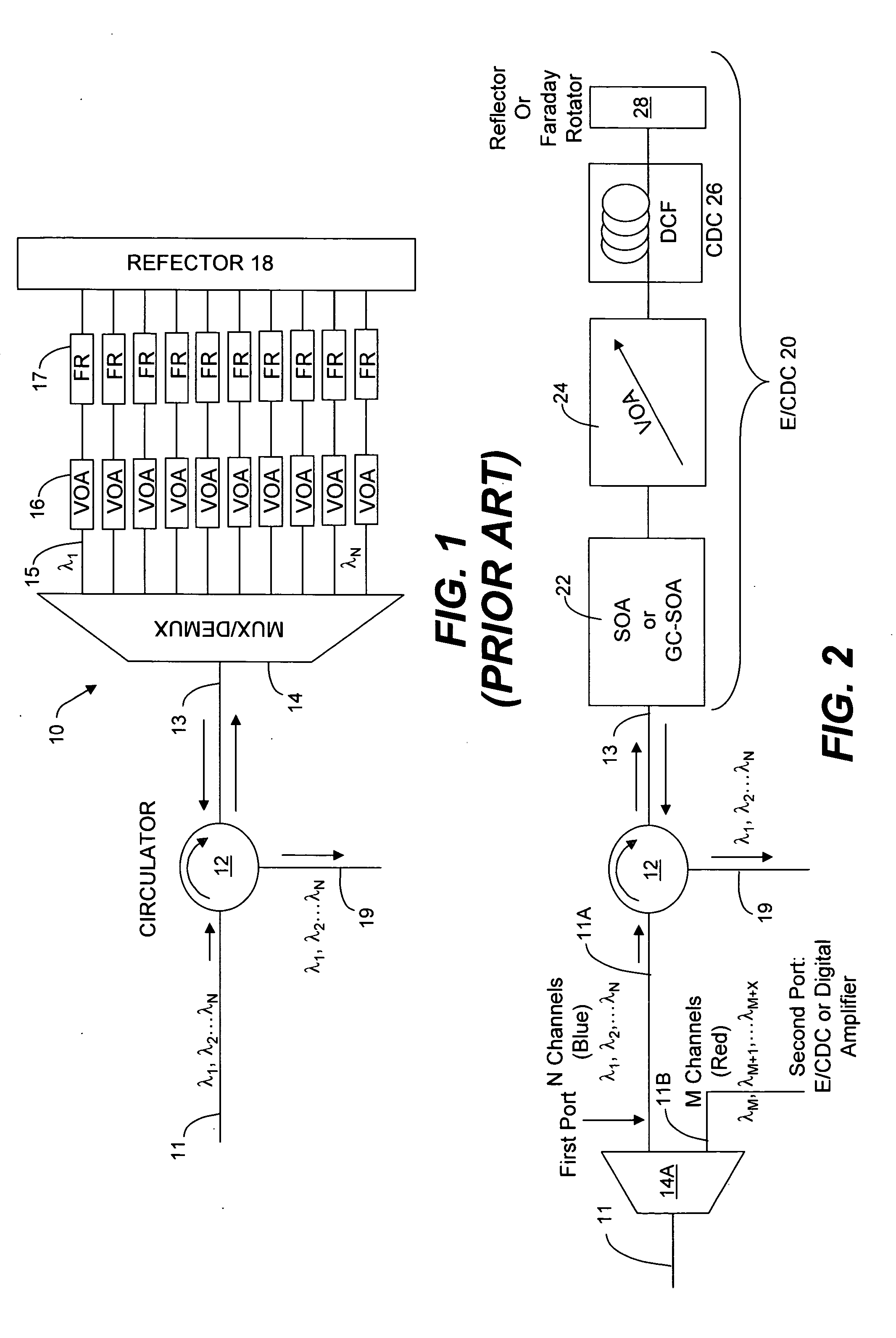
[0036] Reference is now made to FIG. 2 which illustrates a first embodiment of this invention comprising equalizer / chromatic dispersion compensator (E / CDC) 20. The incoming wavelength bands of multiplexed signals on optical transmission span 11 of an optical transmission network are received at channel signal band demultiplexer 14A were N channels, λ1, λ2, . . . , λN, that are in a low wavelength band of wavelengths, such as the low end of the C band, are received at a first port on fiber line 11A. On the other hand, M channels, λM, λM+1, . . . , λM+X, that may be of a higher wavelength band of wavelengths in the C band or a group of wavelengths in the L band, are received at a second port on fiber line 11B. N channels, λ1, λ2, . . . , λN, are provided, via optical circulator 12, onto input fiber 13 to E / CDC 20. While circulator 12 is shown as a coupling element for transferring and receiving signals, λ1, λ2, . . . , λN, it is well known in the art that other optical components may ...


PUM


Abstract

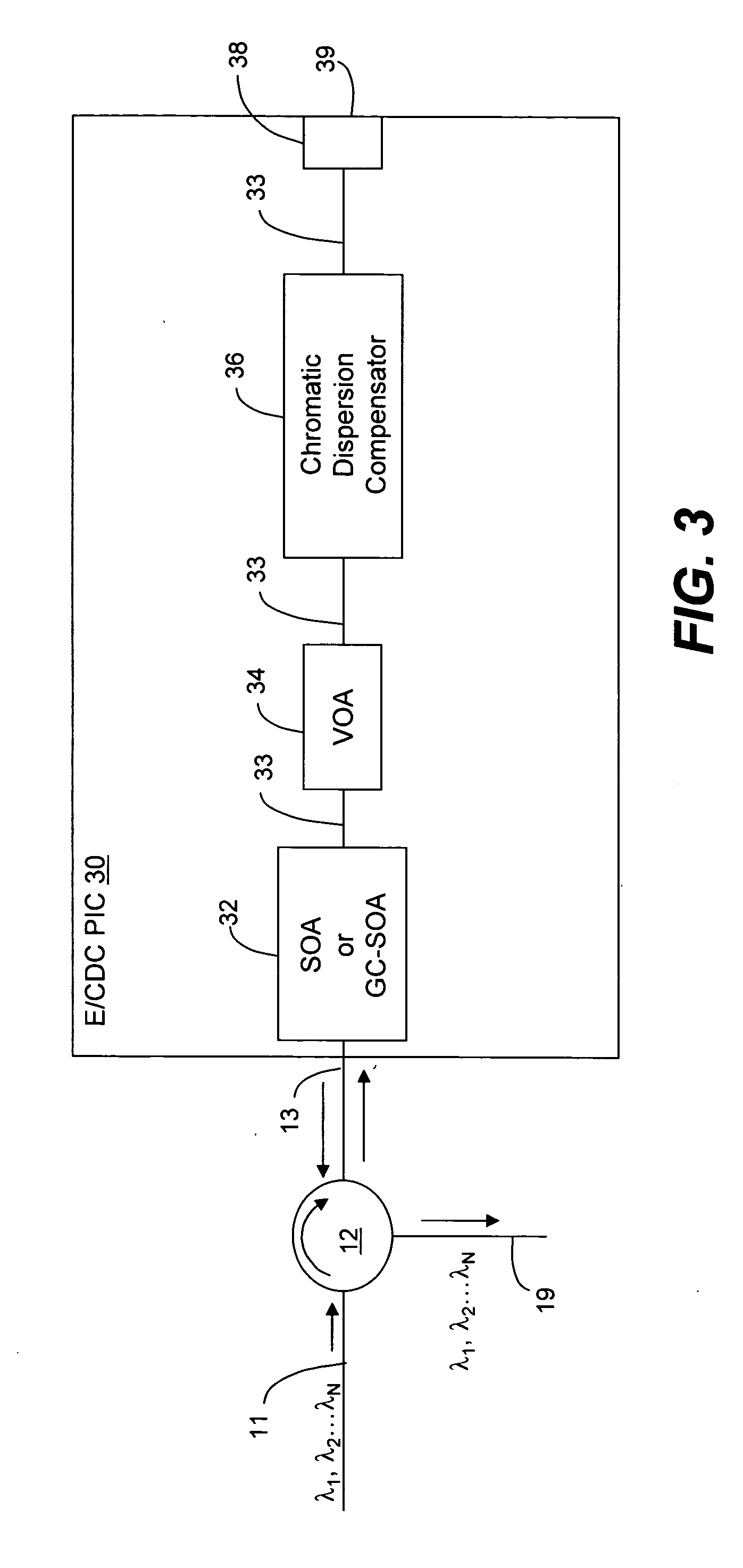
An optical equalizer / dispersion compensator (E / CDC) comprises an input / output for receiving a multiplexed channel signal comprising a plurality of channel signals of different wavelengths. An optical amplifier may be coupled to receive, as an input / output, the multiplexed channel signals which amplifier may be a semiconductor optical amplifier (SOA) or a gain clamped-semiconductor optical amplifier (GC-SOA). A variable optical attenuator (VOA) is coupled to the optical amplifier and a chromatic dispersion compensator (CDC) is coupled to the variable optical attenuator. A mirror or Faraday rotator mirror (FRM) is coupled to the chromatic dispersion compensator to reflect the multiplexed channel signal back through optical components comprising the chromatic dispersion compensator, the variable optical attenuator and the optical amplifier so that the multiplexed channel signal is corrected partially for equalization and chromatic dispersion compensation with respect to each pass through these optical components. The E / CDC components may be integrated in a photonic integrated circuit (PIC) chip. In several embodiments, a photonic integrated circuit (PIC) chip comprises an input into the chip that receives at least one channel signal having experienced chromatic dispersion, a chromatic dispersion compensator (CDC) that separates the at least one channel signal into separate wavelength components over a free spectral range (FSR) spanning only a signal channel width and subjects the wavelength components to a phase shift to change the wavelength group delay in the wavelength components and that recombines the wavelength components to reconstitute the at least one channel signal, and an output from the chip for the recombined at least one channel signal having reduced chromatic dispersion compared to the same channel signal received at the chip input. The CDC device may include a tuning section to vary the phase shift of wavelength components as they propagate through the device. Such a CDC device may include a Mach-Zehnder interferometer (MZI) or a cascaded group of Mach-Zehnder interferometers, or at least one arrayed waveguide grating (AWG) or at least one Echelle grating.

Description

REFERENCE TO A RELATED APPLICATION [0001] This application claims priority to provisional application, Ser. No. 60 / 513,452, filed Oct. 22, 2003, which provisional application is incorporated herein by its reference.BACKGROUND OF THE INVENTION [0002] 1. Field of the Invention [0003] This invention relates generally to WDM or DWDM systems with optical signal equalization and / or chromatic dispersion (CD) compensation and / or polarization mode dispersion (PMD) compensation for optical signals and more particularly to optical equalizers / dispersion compensators in photonic integrated circuit (PIC) chips. [0004] 2. Description of the Related Art [0005] t is known in the art to provide for optical signal equalization as well as dispersion compensation relative to optical signals propagating in a WDM optical communication network. By including optical signal equalization as well as optical signal compensation, albeit chromatic dispersion compensation or polarization mode dispersion or both, i...

Claims


Application Information

Patent Timeline
Patent Type & Authority Applications(United States)
IPC IPC(8): G02B6/34H04B10/18
CPCG02B6/12007G02B6/12014G02B6/12019G02B6/12026H04J14/0221G02B6/2793G02B6/29391G02B6/29394H04B10/25133G02B6/12033H04J14/02216
Inventor GRUBB, STEPHEN G.JOYNER, CHARLES H.PETERS, FRANK H.KISH, FRED A. JR.PERKINS, DREW D.
Owner INFINERA CORP
Learn More