
Color filter for liquid crystal display and semitransmission liquid crystal display

a liquid crystal display and color filter technology, applied in the direction of optical filters, instruments, optics, etc., can solve the problems of significantly deteriorating visibility, affecting the color reproduction of transmissive displays, and not achieving significant power consumption improvement from improving transmittance, so as to improve the color reproducibility of transmissive displays, improve color characteristics, and improve color reproducibility.

Inactive Publication Date: 2005-05-26
TORAY IND INC
View PDF10 Cites 37 Cited by
  • Summary
  • Abstract
  • Description
  • Claims
  • Application Information

AI Technical Summary

Benefits of technology

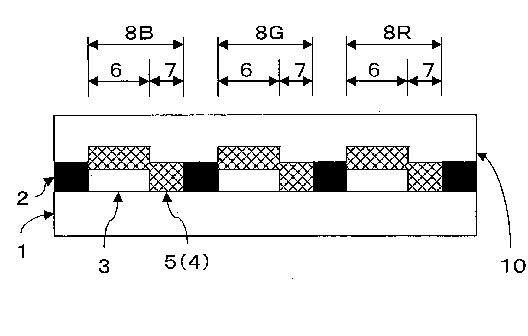
[0012] The present invention has been achieved in consideration of the above problems, and an object of the present invention is to provide a low-cost transflective liquid crystal display capable of a transmissive display having high color reproducibility and a reflective display having excellent characteristics (color reproducibility and brightness). Another object of the present invention is to provide a color filter at low cost, which is capable of removing a difference in chromaticity between a reflective display and a transmissive display of a transflective liquid crystal display to exhibit excellent color characteristics and display characteristics.
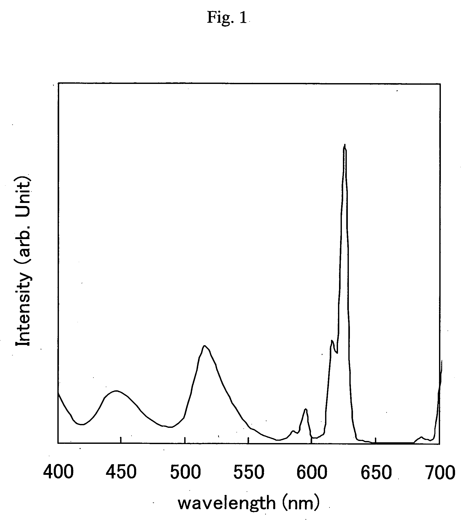
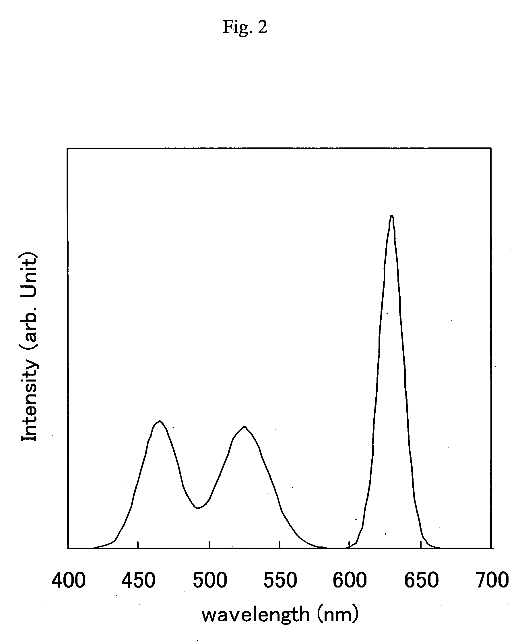
[0029] Although the three-peak type light source is known to improve color reproducibility of a transmissive display, in the present invention, it was found that the three-peak type light source may improve not only the color characteristics of a transmissive display but also the color characteristics of a reflective display using environmental light. In a specified color filter structure, i.e., an area controlling system or thickness controlling system, the color characteristics can be improved. It was also found that in the use of a LED light source as the three-peak type light source, the characteristics of the reflective display can be significantly improved.

Problems solved by technology

Although the transmittance of the color filter is being improved every year, a significant decrease in power consumption is not expected from improvement in transmittance.
However, in a place where sufficient environment light cannot be secured, a display becomes dark, thereby causing. the problem of significantly deteriorating visibility.
However, in the use of such a conventional color filter as shown in FIG. 6, i.e., a color filter in which a reflective region and a transmissive region are not provided in each picture element to cause uniform color characteristics within each picture element, a problem occurs in producing a vivid transmissive display.
Therefore, sufficient visibility cannot be obtained for reflective display.
This problem is due to the fact that in the transmissive display, backlight is transmitted once through the color filter, while in the reflective display, environmental light is transmitted through the color filter two times-including the time of incidence and the time of reflection.
On the other hand, an increase in the degree of thinning of the colored layer in each reflective region causes large variations in the thickness, i.e., large variations in display colors, thereby causing a manufacture problem such as a reduction in yield, or the like.
In this method for improving the color reproducibility in the transmissive display, with the above-described degree of thinning, sufficient brightness cannot be obtained in the reflective display, thereby causing the problem of failing to satisfy both a vivid transmissive display and a bright reflective display.
Also, the problem in which the transmissive display and the reflective display have different color tones cannot be solved only by changing the thickness.
However, in a photolithography method which is a main stream at present, coating of a coloring agent and photolithography process are performed two times or more for forming picture elements of one color, and thus two lithography processes for each color, i.e., a total of six photolithography processes, are required for forming the picture elements of the three colors including red, green and blue, thereby causing the problem of increasing the manufacturing cost.
Therefore, there is the possibility that the product yield is decreased to increase the manufacturing cost of the color filter.
When spaces occur between the reflective regions and the transmissive regions, light leaks from the spaces to decrease the image quality of a liquid crystal display.
On the other hand, when the coloring agents overlap with each other, the color only at the boundaries is increased and is possibly recognized as ununiformity on a screen.
Furthermore, the cell gap of the liquid crystal display becomes defective.
Namely, the yield of the liquid crystal display deteriorates to possibly increase the manufacturing cost of the liquid crystal display.
However, this method decreases the color purity-reflectance characteristics of the reflective display, as compared with the method in which the transmissive regions and the reflective regions are coated separately.
Therefore, this method has the problem of failing to satisfy both color vividness and sufficient brightness.
Particularly, when the color reproducibility is increased in the transmissive display and the reflective display, the brightness of the reflective display is decreased to cause the insufficient performance as a liquid crystal display.
However, a combination with a conventionally known low-cost color filer for a transflective liquid crystal display has the problem of failing to achieve a level in which both the high color reproducibility of the transmissive display and the sufficient brightness of the reflective display are satisfied.

Method used


Image

  • Color filter for liquid crystal display and semitransmission liquid crystal display
  • Color filter for liquid crystal display and semitransmission liquid crystal display
  • Color filter for liquid crystal display and semitransmission liquid crystal display

Examples


example 1

[0100] A. Formation of Polyamic Acid Solution

[0101] 95.1 g of 4,4′-diaminodiphenyl ether and 6.2 g of bis(3-aminopropyl)tetramethyl disiloxane were charged together with 525 g of γ-butyrolactone and 220 g of N-methyl-2-pyrrolidone, and 144.1 g of 3,3′,4,4′-biphenyltetracarboxylic acid dianhydride was added to the resultant mixture. After reaction at 70° C. for 3 hours, 3.0 g of phthalic anhydride was added to the reaction solution, followed by further reaction at 70° C. for 2 hours to obtain a 25 wt % solution of polyamic acid (PAA).

[0102] B. Synthesis of Polymer Dispersant

[0103] 161.3 g of 4,4′-diaminobenzanilide, 176.7 g of 3,3′-diaminodiphenyl sulfone and 18.6 g of bis(3-aminopropyl)tetramethyl disiloxane were charged together with 2667 g of γ-butyrolactone and 527 g of N-methyl-2-pyrrolidone, and 439.1 g of 3,3′,4,4′-biphenyltetracarboxylic acid dianhydride was added to the resultant mixture. After reaction at 70° C. for 3 hours, 2.2 g of phthalic anhydride was added to the r...

example 2

[0120] A color filter substrate was formed by the same method as in Example 1 except that photomasks having aperture region ratios of 14%, 43% and 18% were used for photolithography of red, green and blue picture elements, respectively. Then, an over coat layer and an ITO film were deposited on the resultant picture element film by the same method as in Example 1. For the thus-formed color filter substrate, the spectrum of each of the central picture element and the four corner picture elements of the substrate was measured. The measured spectra of the picture elements were averaged.

example 3

[0125] A color filter substrate was formed by the same method as in Example 1 except that a colored film of each of red, green and blue picture elements was deposited to a thickness of 1.1 μm, and photomasks having aperture region ratios of 10%, 27% and 10% were used for photolithography of red, green and blue picture elements, respectively. As a result of measurement of the transmissive region chromaticity of each of the red, green and blue picture elements by using standard light source C, the degrees of chromaticity (x, y) of the red, green and blue picture elements were (0.551, 0.305), (0.324, 0.531), and (0.139, 0.135), respectively. Then, an over coat layer and an ITO film were deposited on the resultant picture element film by the same method as in Example 1. For the thus-formed color filter substrate, the spectrum of each of the central picture element and the four corner picture elements of the substrate was measured. The measured spectra of the picture elements were averag...


PUM

PropertyMeasurementUnit
transmittanceaaaaaaaaaa
thicknessaaaaaaaaaa
particle diameteraaaaaaaaaa

Abstract

The present invention provides a low-cost transflective liquid crystal display exhibiting high color reproducibility in a transmissive display and excellent characteristics (color reproducibility and brightness) in a reflective display. Also, the present invention provides a color filter for a bright transflective liquid crystal display. The transflective liquid crystal display includes a pair of substrates disposed opposite to each other with a liquid crystal layer held therebetween, a reflection means using ambient light as a light source, and a backlight source. The transflective liquid crystal display further includes a color filter having a transmissive region and a reflective region which are provided in each picture element of the color filter and which have colored layers comprising a single material, and a three-peak type LED backlight source.

Description

TECHNICAL FIELD [0001] The present invention relates to a color filter for a liquid crystal display and a transflective display using the same. BACKGROUND ART [0002] Liquid crystal displays are now used for various applications such as notebook-size PC, mobile terminals, desktop monitors, digital cameras, and the like by making use of the characteristics of the liquid crystal displays, such as light weight, thinness, low power consumption, and the like. In order to further decrease the power consumption of a liquid crystal display using a backlight, the utilization efficiency of the backlight must be improved. Therefore, a color filter is required to have improved transmittance. Although the transmittance of the color filter is being improved every year, a significant decrease in power consumption is not expected from improvement in transmittance. [0003] In recent years, the development of a reflective liquid crystal display not requiring a backlight source having high power consump...

Claims


Application Information

Patent Timeline
Patent Type & Authority Applications(United States)
IPC IPC(8): G02B5/20G02B5/22G02F1/1335
CPCG02B5/223G02F2203/09G02F1/133553G02F1/133516
Inventor YAMASHITA, TETSUOTAKIGUCHI, IKUMIKOJIMA, HIDEYUKISASAKI, HIROYUKI
Owner TORAY IND INC
Learn More