
Method for operation of a power generation plant

Inactive Publication Date: 2005-05-26
ALSTOM TECH LTD
View PDF12 Cites 12 Cited by
  • Summary
  • Abstract
  • Description
  • Claims
  • Application Information

AI Technical Summary

Benefits of technology

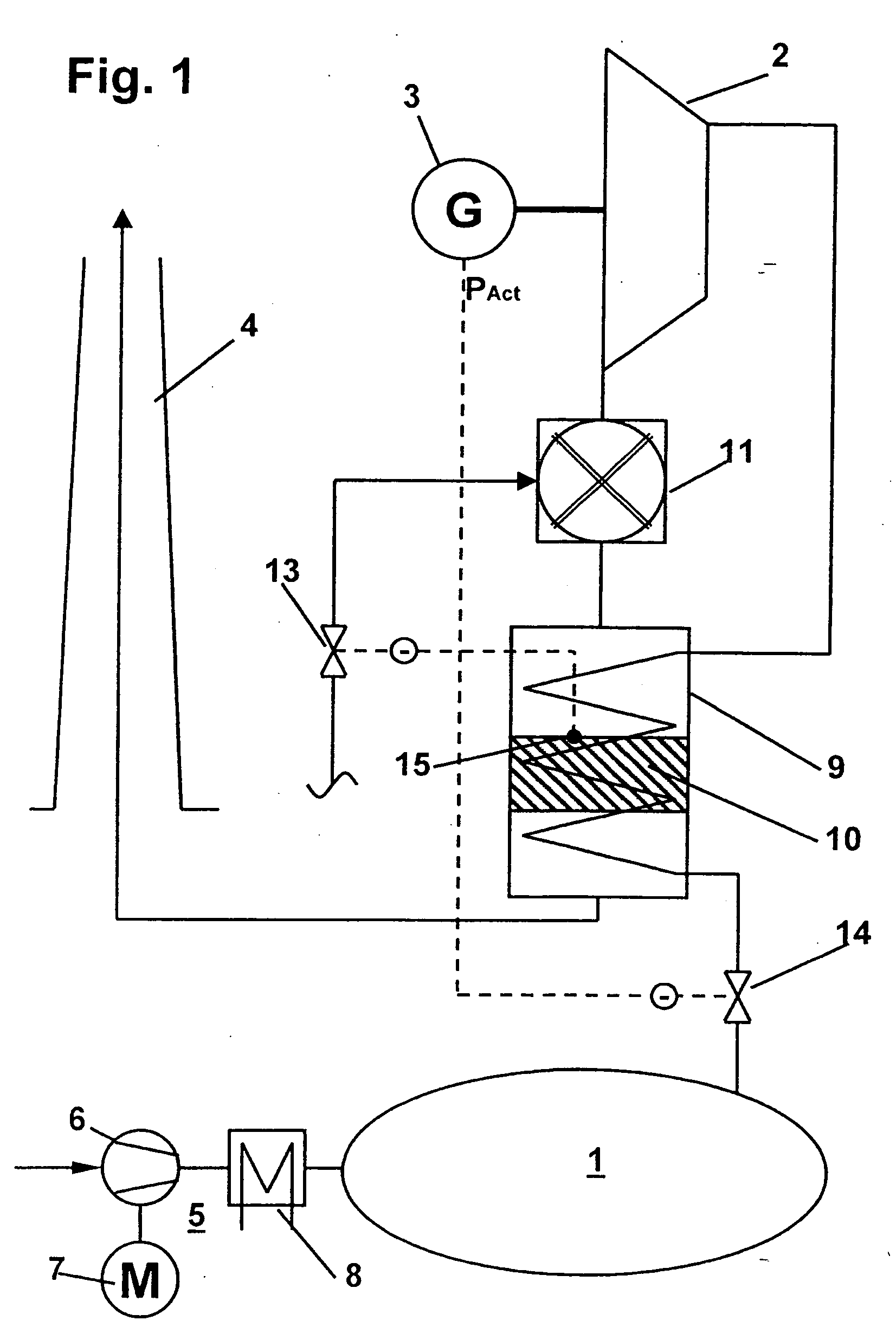
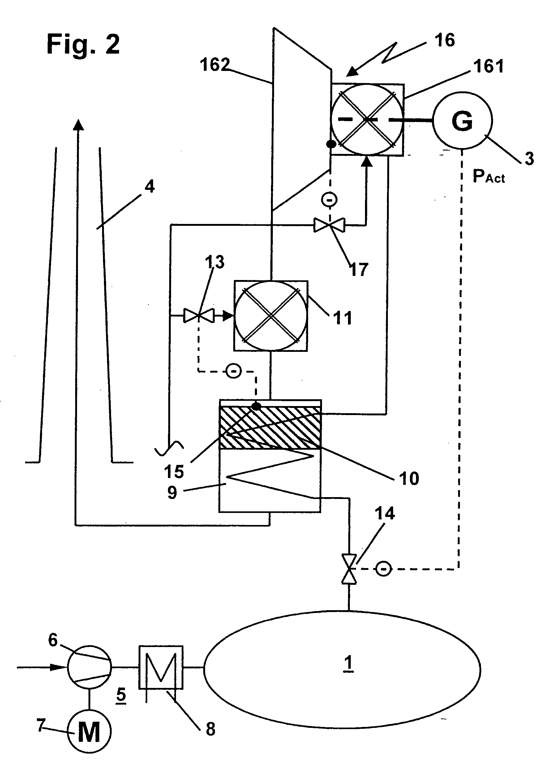
[0007] The inventive arrangement is characterized by several advantages: first, the storage fluid is used directly for combustion of the fuel. This has the advantage that complex equipment for conveying combustion air is eliminated because the expanded storage fluid must flow through an exhaust line of the power engine anyway. Furthermore, it is possible to eliminate an additional flue to be set up next to an exhaust air flue. On the other hand, combustion only takes place downstream from the power engine, and the storage fluid entering the power engine is heated in indirect heat exchange. This means that the power engine has storage fluid flowing through it, and this fluid is usually air instead of corrosive flue gases. It is thus possible to eliminate any protective measures against corrosive flue gases. Therefore, it is possible to use very low-cost power engines than would be the case if the power engines were to be exposed to flue gases. In particular, with slight modifications, steam turbines can be used as the expansion engines for the storage fluid. It is advantageous here if the inlet temperature of the storage fluid is limited to remain compatible with the admissible inlet temperatures of the turbine of, for example, approximately 500° C. to 600° C. or even 650° C. without the use of high-temperature materials. A turbine which is provided for expansion of a non-corrosive storage fluid and therefore does not require special measures for protection against aggressive and corrosive media is hereinafter referred to simply as an air turbine.
[0008] The inventive power plant can be implemented very advantageously and at a low cost with precisely a single expansion engine. In an advantageous embodiment, the secondary-side flow path of the heat transfer apparatus through which pressurized storage fluid flows is essentially in direct fluid connection with the high-pressure side of the expansion engine, such that the heated storage fluid flows to the expansion machine without flowing through additional units. In addition, an essentially direct fluid connection of the low-pressure side of the expansion engine to the atmospheric combustion chamber is established to advantage in precisely this sense. Another advantage is the obligatory compatibility of the fluid mass flows through the heat transfer apparatus on the primary and secondary sides on the basis of which the temperature conditions at the inlet and outlet of the heat exchanger apparatus are essentially only a function of its dimensions.
[0009] It is extremely advantageous to provide a flue gas purification catalyst downstream from the atmospheric combustion chamber. On the basis of the temperature window required for the function of the catalyst, it is advantageously situated within the heat transfer apparatus, namely at a point where the flue gases coming from the atmospheric combustion chamber have cooled far enough in heat exchange with the pressurized storage fluid to prevent damage to the catalyst while still having a temperature suitable to ensure an adequate catalytic effect. In other words, the catalyst is situated downstream from the first part of the primary-side flow path and upstream from the second part within the primary-side flow path of the heat transfer apparatus.
[0014] In yet another advantageous embodiment, the temperature of the flue gas is determined downstream from the primary-side flow path of the heat transfer apparatus or at its outlet and is regulated at a setpoint or at maintaining an allowed minimum. This makes it possible to ensure first that the temperature will not fall below the dew point of corrosive flue gas components. In this regard, the lower limit temperature may also vary depending on the fuel and may be higher with oil firing, for example, than with natural gas firing. In one mode of operation the flue gas temperature may be regulated at the lowest possible value above this dew point, thereby minimizing exhaust heat losses and thus improving fuel utilization.

Problems solved by technology

This requires complex equipment because multiple power engines and multiple heat exchangers must be in fluid connection in series.

Method used


Image

  • Method for operation of a power generation plant
  • Method for operation of a power generation plant
  • Method for operation of a power generation plant

Examples


Embodiment Construction

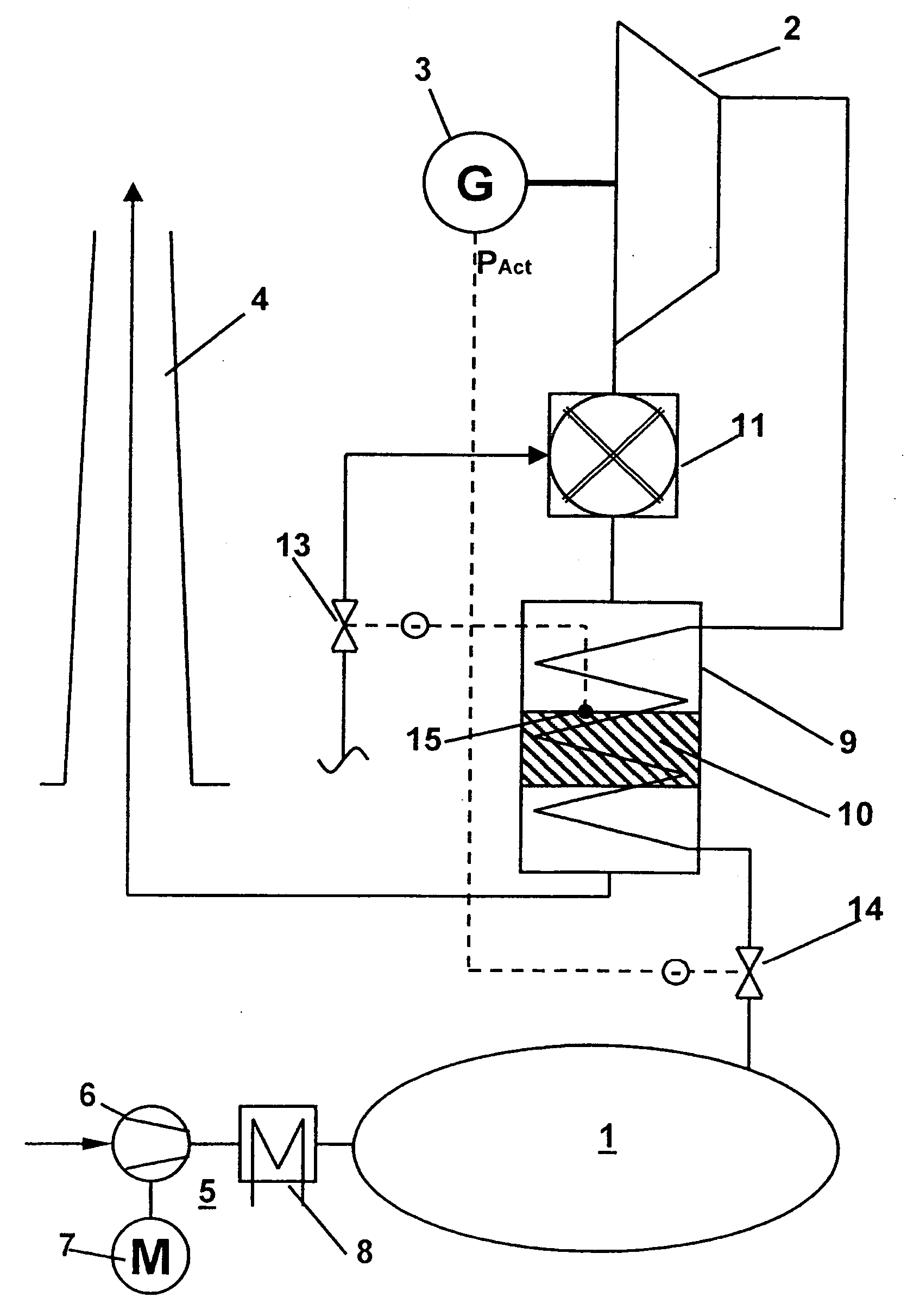
[0022] The power plant depicted in FIG. 1 comprises fundamentally a storage volume 1 for storage of a compressed gas, in particular air, and a turbine 2 for expansion of the storage fluid in a work-producing process, which drives a generator 3 that generates a useful output power PAct. The expanded storage fluid is discharged into the atmosphere through an exhaust flue 4. For loading the storage 1, a compressor unit 5 is provided, although its specific design is not relevant to this invention. A turbocompressor 6 with a drive motor 7 and a condenser 8 are shown as an example. In times of low electric power demand and low electricity price rates accordingly, the compressor unit is operated to load the storage 1 with compressed air. As mentioned in the introduction, and as is easily reproducible, the specific enthalpy gradient over the turbine is very low if air flows from the storage to the turbine 2 and is expanded at approximately ambient temperature. In other words, to generate a ...


PUM


Abstract

A CAES plant comprises an atmospheric combustion chamber situated downstream from the expansion machine. The flue gas produced in the process passes through a heat exchanger. In the heat exchanger, the storage fluid, which flows to the expansion machine from the storage, is heated by heat exchange. In the inventive power plant, the storage fluid is used directly for combustion of a fuel without exposing the expansion machine to corrosive flue gases.

Description

CROSS-REFERENCE TO RELATED APPLICATIONS [0001] This application is a continuation-in-part of the U.S. National Stage designation of co-pending International Patent Application PCT / CH03 / 00431 filed Jun. 30, 2003, the entire content of which is expressly incorporated herein by reference thereto. This application also claims priority to Swiss application no. 2002 1177 / 02 filed Jul. 4, 2002 and Swiss application no. 2003 1812 / 03 filed Oct. 23, 2003, the entire contents of which are expressly incorporated herein by reference thereto.FIELD OF THE INVENTION [0002] The present invention relates to a power plant and a preferred method of operation. BACKGROUND OF THE INVENTION [0003] CAES power plants are sufficiently well known in the state of the art, e.g., from U.S. Pat. No. 5,537,822. In these power plants, a storage volume is filled with a compressed storage fluid, in particular air. At times of peak power demand, the stored fluid is expanded in a power engine to produce energy which dri...

Claims


Application Information

Patent Timeline
IPC IPC(8): F02C7/00
CPCY02E60/15F02C6/16F02C1/06Y02E60/16
Inventor ALTHAUS, ROLFKOLLER, MARTINWIEDERHOLD, KARL
Owner ALSTOM TECH LTD
Learn More