
Device for inductively supplying power and guiding a mobile object

a mobile object and inductive technology, applied in the direction of inductance, non-vehicle mounted steering control, process and machine control, etc., can solve the problems of inability to accurately determine the position uneven travel surface, inevitable mechanical wear of the control surface, etc., to achieve noise-free data reception, precise position determination, and better concentration

Active Publication Date: 2005-05-19
CONDUCTIX WAMPFLER
View PDF8 Cites 27 Cited by
  • Summary
  • Abstract
  • Description
  • Claims
  • Application Information

AI Technical Summary

Benefits of technology

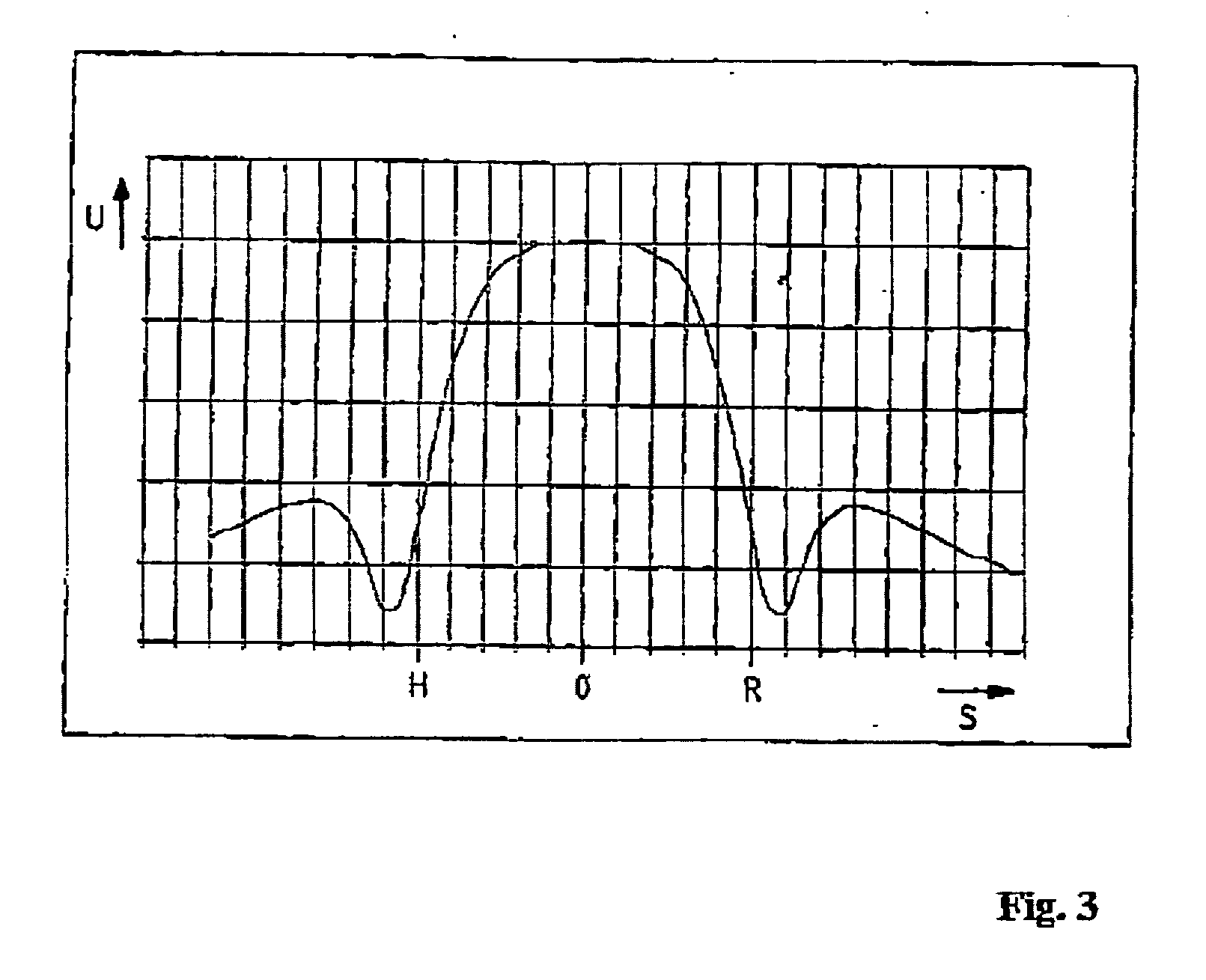
[0011] One essential advantage of the invention is that the inductances otherwise necessary for determining the position on the moving load are simultaneously used for data reception, i.e., only a single inductive antenna is needed for both guidance and data reception. Here, an arrangement of two rows of flat coils, which are offset relative to each other and which are arranged on the moving load transverse to the direction of motion and with the vertical axis direction, is especially suitable. Such flat coils can be easily mounted on a printed-circuit board, and, in the extreme case, they could even be realized completely planar on a printed-circuit board. [0012] i) When this receiver coil arrangement is wide enough to cover at least one of the conductors of the conductor loop used for power transmission on the sides, and the data line is adjacent to a line of the loop, even in curved section of the path over which the load moves, both a precise position determination and also a coupling of at least one receiving inductance with the data line sufficient for noise-free data reception is always guaranteed. This also applies when the antenna cannot be arranged in the center of the articulated front axle of the moving load and thus experiences a lateral deflection in a curve. Here, the line position can be determined very precisely from a comparison of the measurement signals of the individual receiver coils or from an interpolation of the amplitude profile between the individual receiver coils.
[0012] i) When this receiver coil arrangement is wide enough to cover at least one of the conductors of the conductor loop used for power transmission on the sides, and the data line is adjacent to a line of the loop, even in curved section of the path over which the load moves, both a precise position determination and also a coupling of at least one receiving inductance with the data line sufficient for noise-free data reception is always guaranteed. This also applies when the antenna cannot be arranged in the center of the articulated front axle of the moving load and thus experiences a lateral deflection in a curve. Here, the line position can be determined very precisely from a comparison of the measurement signals of the individual receiver coils or from an interpolation of the amplitude profile between the individual receiver coils.
[0013] In principle, the receiving inductances could also be used for transmitting data signals, but it appears to be more advantageous to provide for this purpose a separate arrangement of inductances with ferromagnetic cores to concentrate the field better to the data line, wherein, here, two rows of inductances offset relative to each other also represent an especially preferable solution. Both in terms of the transmitting inductances and also the receiving inductances, the one that features the best coupling for the data line due to their instantaneous lateral position is selected for the communication operation on the basis of the result of the position determination. This process can be applied, in principle, to any inductive antenna arrangement with several transmitter and / or receiver coils.

Problems solved by technology

Disadvantages of this solution include the labor required to cut the groove, the unevenness of the travel surface, and the inevitable mechanical wear of the control surface.

Method used


Image

  • Device for inductively supplying power and guiding a mobile object
  • Device for inductively supplying power and guiding a mobile object
  • Device for inductively supplying power and guiding a mobile object

Examples


Embodiment Construction

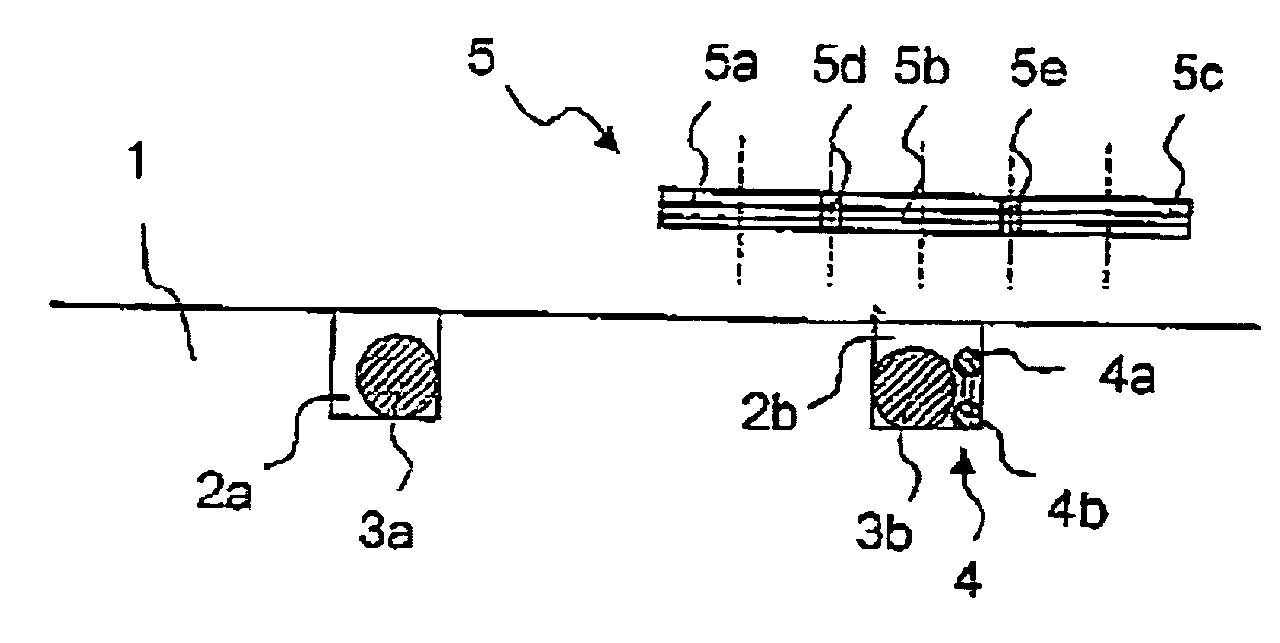
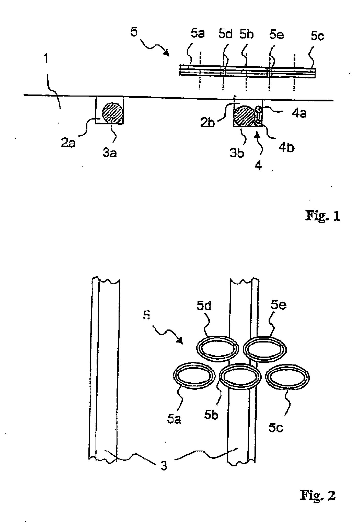
[0023] In FIGS. 1 and 2, a part of a device according to the invention is shown schematically in cross section and in top view, respectively. Two grooves 2a and 2b are cut into a track 1, on which an electric transport vehicle is to move. The forward conductor 3a and the return conductor 3b of a conductor loop 3 are embedded in these grooves 2a and 2b. Only a short section of this loop can be seen in FIG. 2. The conductor loop 3 is powered by power supply electronics (not shown) and acts as a spatially distributed primary inductance of a transformer, whose secondary inductance is formed by a load mounted on the vehicle. In this way, the vehicle is supplied with the electrical energy required for its operation. The load and the vehicle are not of interest here and are thus not shown in the figures. Typical operating parameters of such a system are 100 mm for the primary line center spacing, 10 mm for the air gap, 100 A for the current, and 20 kHz for the frequency.

[0024] In addition...


PUM

PropertyMeasurementUnit
frequencyaaaaaaaaaa
distanceaaaaaaaaaa
intrinsic impedanceaaaaaaaaaa

Abstract

Device for inductive power supply and guidance of a moving object, with a primary inductance element extending as a conductive loop along a path provided for the object. A secondary inductance element is arranged on the object and can be coupled magnetically with the primary inductance element for power transmission. Several receiver inductance elements are arranged on the object and output measurement signals dependent on the magnetic field of the primary inductance element. An evaluation device determines a measure for the position of the object with reference to the conductive loop from the measurement signals. A regular arrangement of receiver inductance elements is provided, which extends on the object at least perpendicular to its direction of motion. The receiver inductance elements are simultaneously also connected to a data receiver device, which contains a way for extracting a data signal from the output voltage of at least one of the receiver inductance elements. At least one data line, which exhibits inductive coupling with at least one of the receiver inductance elements sufficient for transmitting a data signal while the object is moving, is arranged along the path provided for the object.

Description

RELATED APPLICATION [0001] This application is a continuation of International Application PCT / EP03 / 01713, filed Feb. 20, 2003, the contents of which are here incorporated by reference in their entirety. Applicants claim the benefit of 35 USC §120.BACKGROUND OF THE INVENTION [0002] 1. Field of the Invention [0003] The invention pertains to a device for inductively supplying power and guiding a mobile object. [0004] 2. Prior Art [0005] The inductive transmission of power enables power to be supplied to a mobile load without mechanical or electrical contact. Devices provided for this purpose, like those known, e.g., from WO 92 / 17929, include a primary part and a secondary part, which are electromagnetically coupled similarly in principle to a transformer. The primary part consists of supply electronics and a conductor loop laid along a path with forward and return conductors, which extend parallel to each other and transition into each other or are connected to each other at the end o...

Claims


Application Information

Patent Timeline
Patent Type & Authority Applications(United States)
IPC IPC(8): B60L5/00G05D1/02H01F38/14H02J5/00H04B5/00
CPCB60L5/005G05D1/0265H01F38/14H02J5/005Y02T90/16Y02T10/7005Y02T90/121Y02T90/163Y02T90/14Y02T90/128B60L11/1833B60L11/1838B60L2200/26Y02T90/125Y02T10/7072B60L53/12B60L53/38B60L53/36Y02T90/12Y02T10/70H02J50/90H02J50/10B60L5/00
Inventor GREEN, ANDREWBOHLER, FRANKWINTERHALTER, ROLAND
Owner CONDUCTIX WAMPFLER
Learn More