
Damped biphasic energy delivery circuit for a defibrillator

a biphasic energy and defibrillator technology, applied in the field of electrotherapy circuits, can solve the problems of reducing the effect of defibrillator pulse, ineffective heart pumping, and severe reduction of heart pumping, and affecting the defibrillator puls

Inactive Publication Date: 2005-05-12
KONINKLIJKE PHILIPS ELECTRONICS NV
View PDF61 Cites 25 Cited by
  • Summary
  • Abstract
  • Description
  • Claims
  • Application Information

AI Technical Summary

Benefits of technology

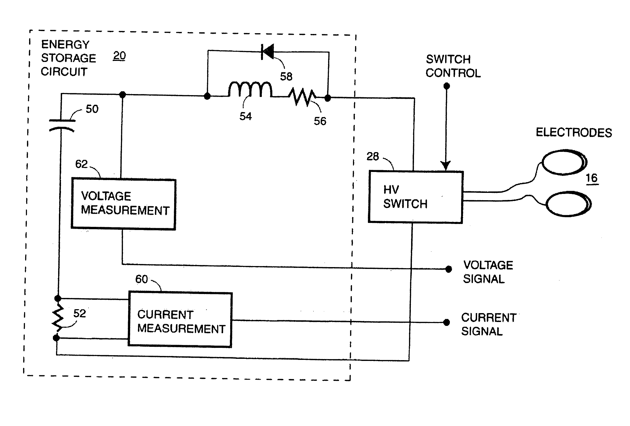
[0012] More recent biphasic defibrillator designs such as the Heartstream Forerunner® automatic external defibrillator (AED) utilize solid state switches such as silicon controlled rectifiers (SCRs) and insulated gate bipolar transistors (IGBTs) connected in an H-bridge to produce a biphasic truncated exponential (BTE) defibrillation pulse. Such solid state switches require snubber circuits in series with the energy storage capacitor to control the rate of change of voltage or current through the switches to prevent switch damage as well as to prevent false triggering from transient energy. The snubber circuit in the Forerunner AED employs a 150 microHenry (uH) inductor. Similarly, in U.S. Pat. No. 5,824,017, “H-Bridge Circuit For Generating A High-Energy Biphasic Waveform In An External Defibrillator”, issued Oct. 20, 1998, to Sullivan et al., a protective element having resistive and inductive properties is interposed between the energy storage capacitor and the H bridge. Sullivan et al teach that the protective element 27 is used to the limit the rate of change of voltage across, and current flow to, the SCR switches of the H bridge. However, snubber circuits, while designed to protect the switch components of the H-bridge, do not address the problem of limiting peak current to the patient across the range of patient impedances.

Problems solved by technology

In VF, the normal rhythmic ventricular contractions are replaced by rapid, irregular twitching that results in ineffective and severely reduced pumping by the heart.
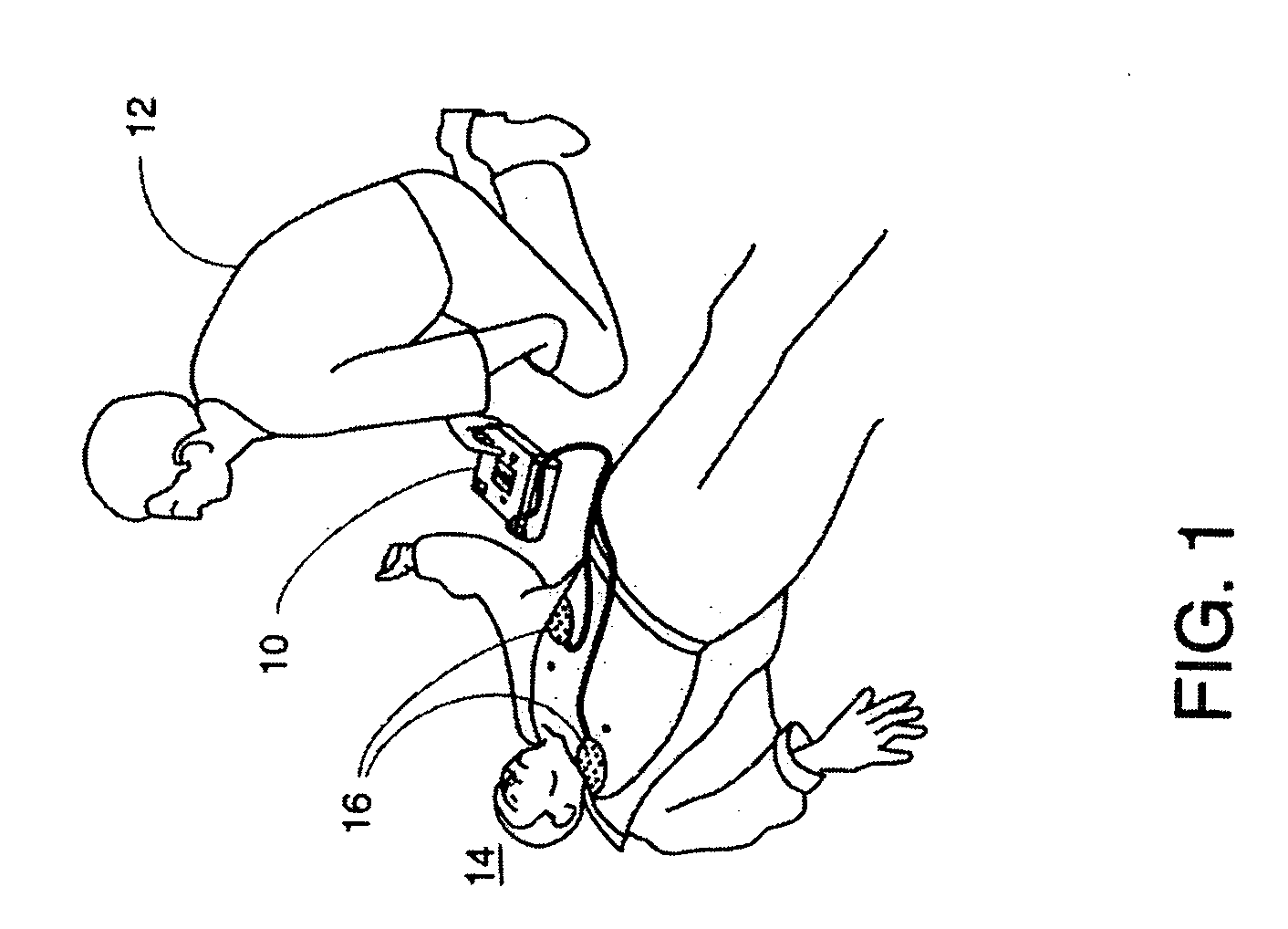
If the peak current of the defibrillation pulse that is delivered to the patient 14 exceeds the maximum value, damage to tissue and decreased efficacy of the defibrillation pulse will likely result.
Using a single capacitor to provide the defibrillation pulse at adequate energy levels across the entire range of patient impedances can result in higher than necessary peak currents being delivered to patients with low patient impedances.
Using current limiting resistors to limit peak current as taught by the prior art results in substantial amounts of power being dissipated in the resistors which increases the energy requirements on the defibrillator battery.
Furthermore, such prior art circuits require complex, active control systems to regulate the current during the delivery of the defibrillation pulse.
RLC defibrillator designs according to the prior art do not address the problem of limiting peak currents or otherwise compensating for the range of patient impedances.
However, snubber circuits, while designed to protect the switch components of the H-bridge, do not address the problem of limiting peak current to the patient across the range of patient impedances.

Method used


Image

  • Damped biphasic energy delivery circuit for a defibrillator
  • Damped biphasic energy delivery circuit for a defibrillator
  • Damped biphasic energy delivery circuit for a defibrillator

Examples


Embodiment Construction

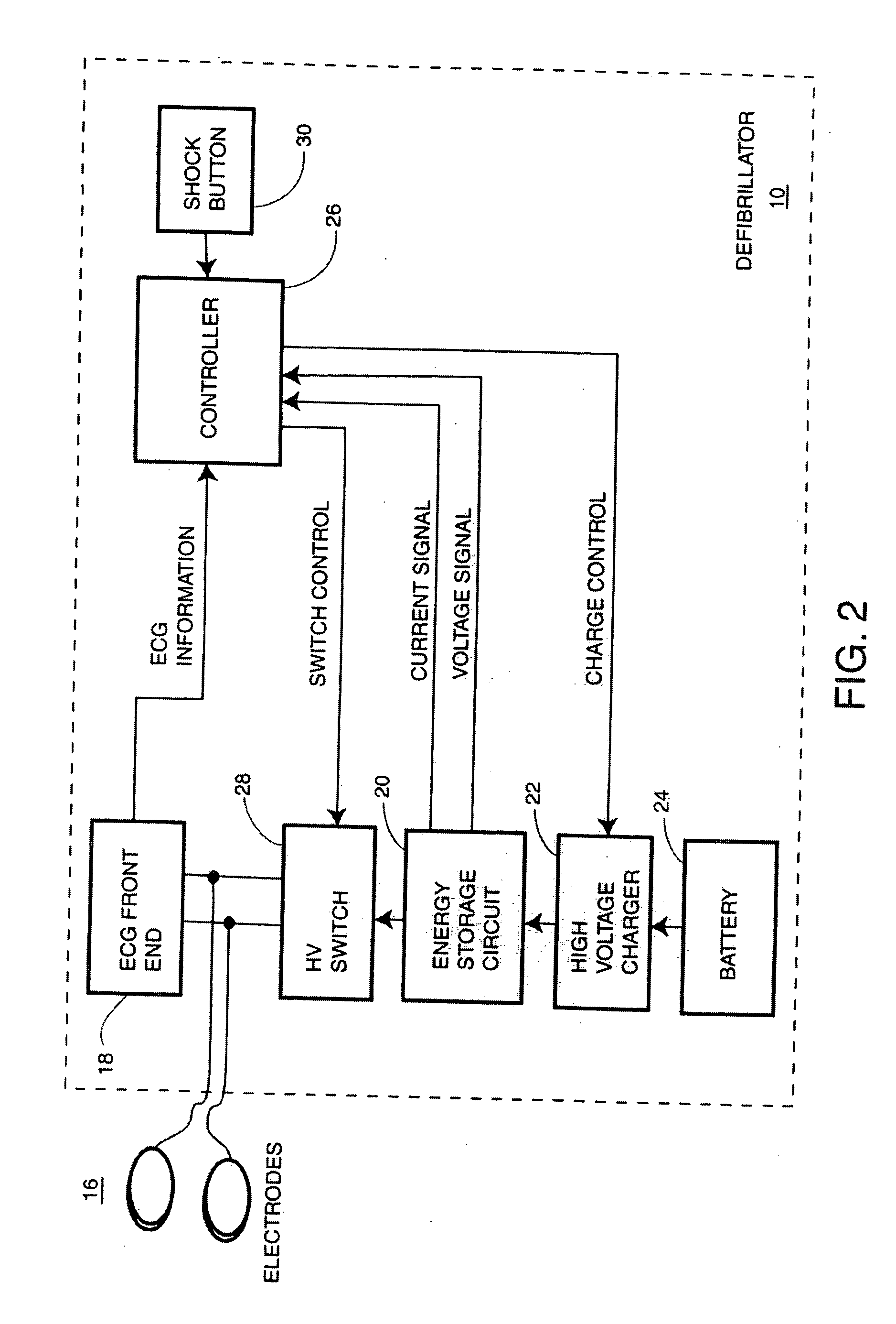
[0029]FIG. 2 is a simplified block diagram of a defibrillator 10 according to the present invention. The pair of electrodes 16 for coupling to the patient 14 are connected to an ECG front end 18 and further connected to an HV switch 28. The ECG front end 18 provides for detection, filtering, and digitizing of the ECG signal from the patient 14. The ECG signal is in turn provided to a controller 26 which runs a shock advisory algorithm that is capable of detecting ventricular fibrillation (VF) or other shockable rhythm that is susceptible to treatment by electrotherapy.

[0030] A shock button 30, typically part of a user interface of the defibrillator 10 allows the user to initiate the delivery of a defibrillation pulse through the pair of electrodes 16 after the controller 26 has detected VF or other shockable rhythm. A battery 24 provides power for the defibrillator 10 in general and in particular for a high voltage charger 22 which charges the capacitors in an energy storage circui...


PUM


Abstract

A defibrillator capable of delivering a damped biphasic truncated (DBT) defibrillation pulse is provided. An energy storage circuit is coupled across a high voltage switch such as an H-bridge for delivering a defibrillation pulse to the patient through a pair of electrodes. A controller operates to control the entire defibrillation process and detects shockable rhythms from the patient via an ECG front end. The energy storage circuit consists of an energy storage capacitor, a series inductor, a shunt diode, and optionally a resistor in series with the inductor. The controller measures as the patient dependent parameter the time interval between the initial delivery of the defibrillation pulse and the occurrence of the peak current or voltage to determine the first and second phases of the defibrillation pulse to provide for compensation for patient impedance. Other types of patient dependent parameters, measured either before or during delivery of the DBT defibrillation pulse, could be alternatively employed to achieve the impedance compensation.

Description

[0001] This is a continuation in part of U.S. patent application Ser. No. 10 / 124,062 filed Apr. 17, 2002, which is a divisional application of U.S. patent application Ser. No. 09 / 299,456 filed Apr. 22, 1999 and now U.S. Pat. No. 6,405,081.[0002] This invention relates to electrotherapy circuits and in particular to a defibrillator which is capable of applying damped biphasic defibrillation pulses to a patient. [0003] Electro-chemical activity within a human heart normally causes the heart muscle fibers to contract and relax in a synchronized manner that results in the effective pumping of blood from the ventricles to the body's vital organs. Sudden cardiac death is often caused by ventricular fibrillation (VF) in which abnormal electrical activity within the heart causes the individual muscle fibers to contract in an unsynchronized and chaotic way. The only effective treatment for VF is electrical defibrillation in which an electrical shock is applied to the heart to allow the heart...

Claims


Application Information

Patent Timeline
Patent Type & Authority Applications(United States)
IPC IPC(8): A61N1/39
CPCA61N1/39A61N1/3937A61N1/3912A61N1/3904
Inventor LYSTER, THOMAS D.GLINER, BRADFORD E.POWERS, DANIEL J.
Owner KONINKLIJKE PHILIPS ELECTRONICS NV
Learn More