Detector for sunken condition of vehicle
a technology for detecting the condition of vehicles and sunken vehicles, which is applied in the direction of piers, anti-theft devices, and groynes, etc., can solve the problems of inability to function, technology disclosed, and japanese patent publication tokkai 11 to achieve the effect of quickly and reliably detecting the condition
- Summary
- Abstract
- Description
- Claims
- Application Information
AI Technical Summary
Benefits of technology
Problems solved by technology
Method used
Image
Examples
first embodiment
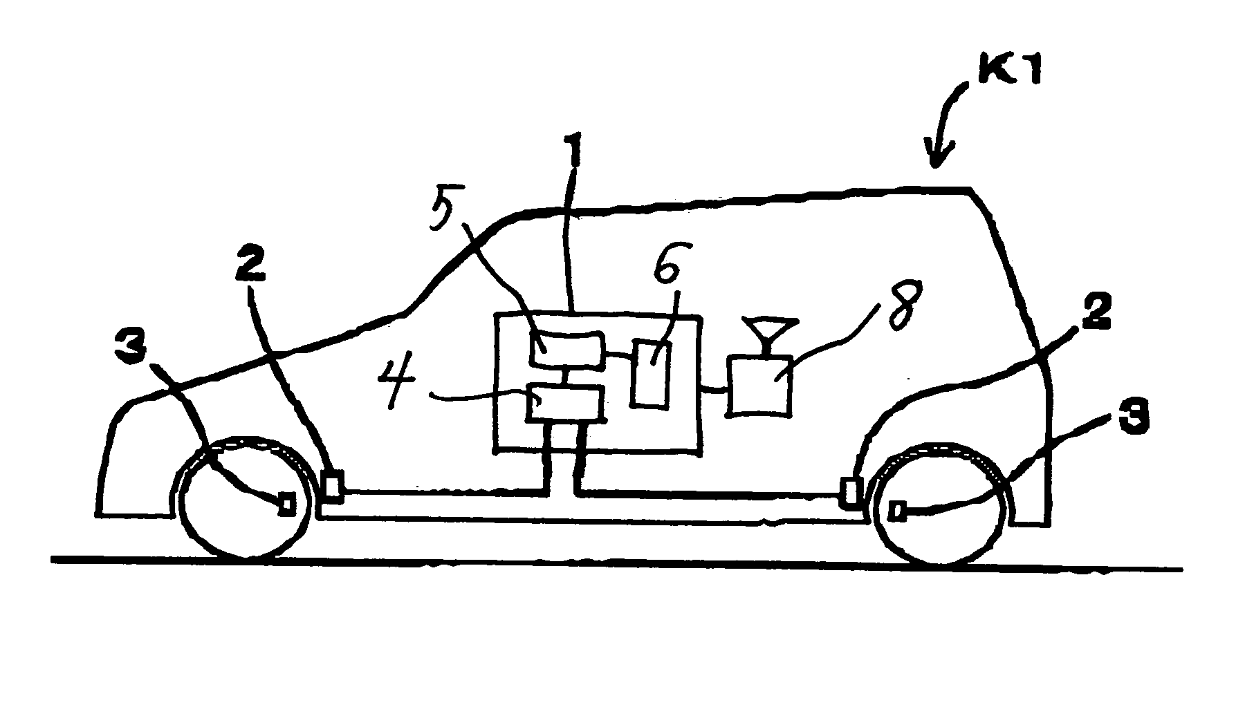
[0028]FIG. 1 shows a four-wheel vehicle K1 provided with a tire pressure monitoring system (TPMS) and a detector according to this invention. The elements that comprise the TPMS include a controller 1, antennas 2 and sensor units 3. The controller 1 is that of the TPMS set inside a control box carried by the vehicle and is provided with a microcomputer and a communication circuit (at least for reception), serving to receive through the antennas 2 wireless signals transmitted periodically from the sensor units 3, to read air pressure data contained in the wireless signals and to output an alarm (by sound, light and / or a character display) to inform the user if, for example, the air pressure value of a tire has dropped below an allowable level. The antennas 2 are each set near a corresponding one of the tires such as inside the tire housing and serve to receive wireless signals from the corresponding one of the sensor units 3, and to input them to the controller 1.
[0029] The sensor un...
second embodiment
[0044] A detector of a sunken condition may be described also by FIG. 1 except that the controller 1 and the sensor units 3 are adapted to carry out two-way telecommunications. In other words, the controller 1 according to this embodiment of the invention is adapted to carry out not only the basic controls as a TPMS but also processes according to the flowchart shown in FIG. 4 to identify a sunken condition of the vehicle.
[0045] To explain more in detail, the controller 1 according to this embodiment of the invention carries out, for example, the processes of the flowchart of FIG. 4 periodically, by initially setting the value of a communication error counter to zero (Step S11) and next checking whether or not the processes of Steps S15-S18 have been completed (Step S12). If the judgment in Step S12 is YES, the controller 1 proceeds to Step S19. If the judgment in Step S12 is NO, the controller proceeds to Step S15.
[0046] In Step S15, the controller sends a request signal to the s...
third embodiment
[0050] the present invention relates to a detector for a vehicle equipped with an electric power steering system (EPS). As shown in FIG. 5, the EPS includes a steering wheel 11 with a steering shaft 11a, a pinion gear 12 connected to the steering wheel 11 through the steering shaft 11a and a rack shaft 13 corresponding to the pinion gear 12, numerals 14 each indicating a tire. The EPS further includes a torque sensor 15 for detecting the steering torque exerted on the steering wheel 11, a motor 16 for generating a steering force, a driving mechanism 17 for transmitting the steering force to the rack shaft 13 and a controller 18 for controlling the current to the motor 16 (or output of the motor 16) according to the detected steering torque. Speed signals indicative of the traveling speed of the vehicle outputted from a speed sensor 19 and power from a battery 20 are also supplied to the controller 18.
[0051] The controller 18 functions not only to carry out the basic processes of an ...
PUM
 Abstract
Description
Claims
Application Information
 - R&D
- Intellectual Property
- Life Sciences
- Materials
- Tech Scout
- Unparalleled Data Quality
- Higher Quality Content
- 60% Fewer Hallucinations
Browse by: Latest US Patents, China's latest patents, Technical Efficacy Thesaurus, Application Domain, Technology Topic, Popular Technical Reports.
© 2025 PatSnap. All rights reserved.Legal|Privacy policy|Modern Slavery Act Transparency Statement|Sitemap|About US| Contact US: help@patsnap.com


