
Aromatic methylidene compound, methylstyryl compound for producing the same, production method therefor, and organic electroluminescent element

a technology of methylstyryl compound and methylstyryl compound, which is applied in the direction of organic semiconductor devices, discharge tube/lamp details, natural mineral layered products, etc., can solve the problems of low brightness, low brightness, and element not widely used in practical use, and achieve high brightness and high durability

Inactive Publication Date: 2005-05-05
PANASONIC CORP
View PDF6 Cites 11 Cited by
  • Summary
  • Abstract
  • Description
  • Claims
  • Application Information

AI Technical Summary

Benefits of technology

The present invention has been made in view of the aforementioned present state of the art of the organic electroluminescent elements. The object of the present invention is to provide an aromatic methylidene compound that is especially useful as materials, especially an luminescent material, that may give an organic electroluminescent element having bright luminescence at low voltage and high durability. The present invention also relates to a methylstyryl compound useful for producing the same, production methods therefor, and an organic electroluminescent element having high brightness and high durability.
The compound represented by the formula (1) according to the present invention is useful as a constituent, particularly as a luminescent material, of an organic electroluminescent element. The compound represented by the formula (2) is an useful intermediate for producing the compound represented by the formula (1). The compounds and the production method therefor provided by the present invention make a great contribution to production of an organic electroluminescent element having high brightness and high durability.

Problems solved by technology

However, the dispersion, electroluminescent element requires high a.c. voltage for driving, and therefore have problems such as complicated driving circuits and low brightness.
Therefore, such an element is not widely put into practical use.
On the other hand, organic electroluminescent elements using the organic materials proposed hitherto still have various problems.
For example, functions of the elements may deteriorate even during storing in either driving or non-driving state.
Such deterioration may cause lowering in luminescence brightness and generation and growth of a non-luminescent region that is called dark spot in driving or non-driving state, which finally lead to a short circuit and rupture of the element.
Such phenomena are considered to be essential problems in the materials used.
Therefore, their practical use is restricted to devices in which a short life may be accepted.
Further, none of the present systems and luminescent materials are suitable for an element for a color display.

Method used


Image

  • Aromatic methylidene compound, methylstyryl compound for producing the same, production method therefor, and organic electroluminescent element
  • Aromatic methylidene compound, methylstyryl compound for producing the same, production method therefor, and organic electroluminescent element
  • Aromatic methylidene compound, methylstyryl compound for producing the same, production method therefor, and organic electroluminescent element

Examples


example 1

Production of Compound No. 1-02 (#1)

1.07 g of tetraethyl 1,2-dimethylnaphthalene-α,α′-diyl-diphosphonate and 1.42 g of 2′-formyl-α-phenylstilbene were dissolved in 10 ml of N,N-dimethylformamide. At 5 to 10° C., 0.65 g of potassium tert-butoxide was gradually added to the reaction over 10 minutes. The reaction mixture was then stirred at room temperature for 24 hours. 10 ml of ethanol and 10 ml of water were then added. The precipitate was recovered by filtration, washed with water and then dried to obtain 1.52 g of pale yellow powders.

The pale yellow powders were then subjected to column chromatography with silica gel as a stationary phase and mixture solvent of toluene and hexane (volume ratio 1:3) as a mobile phase, to obtain a pale yellow glass substance. The substance was then re-crystallized from the mixed solvent of chloroform and ethanol, and vacuum dried at 100° C. to obtain 0.84 g of yellow glass having a strong fluorescence (yield 49%). The elementary analysis of thi...

example 2

Production of Compound No. 1-02 (#2)

3.04 g of diethyl diphenylmethylphosphonate and 1.94 g of 1,2-bis(2-formylstyryl)naphthalene were dissolved in 30 ml of N,N-dimethylformamide. At 5 to 10° C., 1.30 g of potassium tert-butoxide was gradually added to the reaction over 10 minutes. The reaction mixture was then stirred at room temperature for 20 hours. 80 ml of ethanol and 25 ml of water were then added. The precipitate was recovered by filtration, washed with water and then dried to obtain pale yellow powders. The pale yellow powders were treated in the same way as in Example 1, to obtain compound No.1-02.

example 3

Production of Compound No. 1-02 (#3)

0.921 g of 1,2-diformylnaphthalene and 4.06 g of diethyl 2-(2,2′-diphenylvinyl)benzylphosphonate were dissolved in 30 ml of N,N-dimethylformamide. At 5 to 10° C., 1.30 g of potassium tert-butoxide was gradually added to the reaction over 10 minutes. The reaction mixture was then stirred at room temperature for 20 hours. 80 ml of ethanol and 25 ml of water were then added. The precipitate was recovered by filtration, washed with water and then dried to obtain pale yellow powders. The pale yellow powders were treated in the same way as in Example 1, to obtain compound No.1-02.


PUM


Abstract

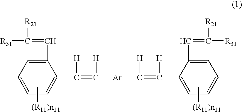
A compound of the formula (1): wherein R11 represents an alkyl group, an alkoxy group, a halogen atom, a cyano group, or a nitro group; n11 is an integer of 0 to 4; R21 and R31 are a hydrogen atom, an alkyl group, a cycloalkyl group, an aromatic group, or a heteroaromatic group; or R21 and R31 together form a condensed ring consisting of aromatic rings or heteroaromatic rings; and Ar is selected from the groups consisting of groups represented by the following formulae: and a methylstyryl compound for producing the same, the production methods thereof and an organic electroluminescent element having the compound.

Description

BACKGROUND OF THE INVENTION The present invention relates to a novel organic methylidene compound useful as functional materials for a sensor in an electronic camera, as functional materials in an organic electroluminescent element such as electric charge transporting materials and luminescent materials, and as functional materials for other various organic semiconductor elements. The present invention also relates to a methylstyryl compound useful for producing the same, production methods therefor, and an organic electroluminescent element. An electroluminescent element utilizing an electroluminescent phenomenon of substances is self-luminescent unlike a liquid crystal element and thus has a high visibility, which results in a clear view when used as a display device. Since the electroluminescent element is completely in a solid state, the element has properties such as shock-resistant property. It is thus expected that the electroluminescent element will find a variety of uses ...

Claims


Application Information

Patent Timeline
IPC IPC(8): C07C13/19C07C15/52C07C15/58C07C15/60C07C15/62C07C22/08C07C25/24C07C43/215C09K11/06H01L51/00H01L51/30H01L51/50
CPCC07C13/19H01L2251/308C07C15/58C07C15/60C07C15/62C07C22/08C07C25/24C07C43/215C07C2101/14C07C2103/24C07C2103/40C09K11/06C09K2211/1003C09K2211/1007C09K2211/1011C09K2211/1029C09K2211/1092H01L51/005H01L51/0052H01L51/0057H01L51/0081H01L51/5012C07C15/52C07C2601/14C07C2603/24C07C2603/40H10K85/60H10K85/625H10K85/615H10K85/324H10K50/11H10K2102/103
Inventor HASHIMOTO, MITSURU
Owner PANASONIC CORP
Learn More