
Housing unit and exposure method using the same

Inactive Publication Date: 2005-05-05
CANON KK
View PDF55 Cites 18 Cited by
  • Summary
  • Abstract
  • Description
  • Claims
  • Application Information

AI Technical Summary

Benefits of technology

[0012] A housing unit according to one aspect of the present invention used to feed an object from a first atmosphere to a second atmosphere different from the first atmosphere includes a support member for supporting the object via a contact surface that contacts the object, and an antislip device that prevents slippery of the object relative to the support member.

Problems solved by technology

On the other hand, an exposure apparatus that uses the EUV light as a light source, which is referred to as an “EUV exposure apparatus” hereinafter, cannot utilize the pellicle film because its material greatly absorbs the exposure light (or the EUV light).
When the reticle that has no pellicle film is being fed, particles adhere to its pattern surface during the feeding of the reticle, for example, during drawing a vacuum (or exhaustion) of a load lock chamber, preventing the exposure light from reflecting and transmitting, and disadvantageously causing exposure defects and lowered yield.
Thus, the support member is likely to damage the reticle when the reticle slips relative to the support member when the cassette is being fed, and surfaces of the support member and / or the reticle are peeled off, causing particles.
In other words, the conventional cassette can protect the reticle from particles outside the cassette, but generate particles inside the cassette and cannot prevent the particles generated inside the cassette from adhering to the reticle.

Method used


Image

  • Housing unit and exposure method using the same
  • Housing unit and exposure method using the same
  • Housing unit and exposure method using the same

Examples


Embodiment Construction

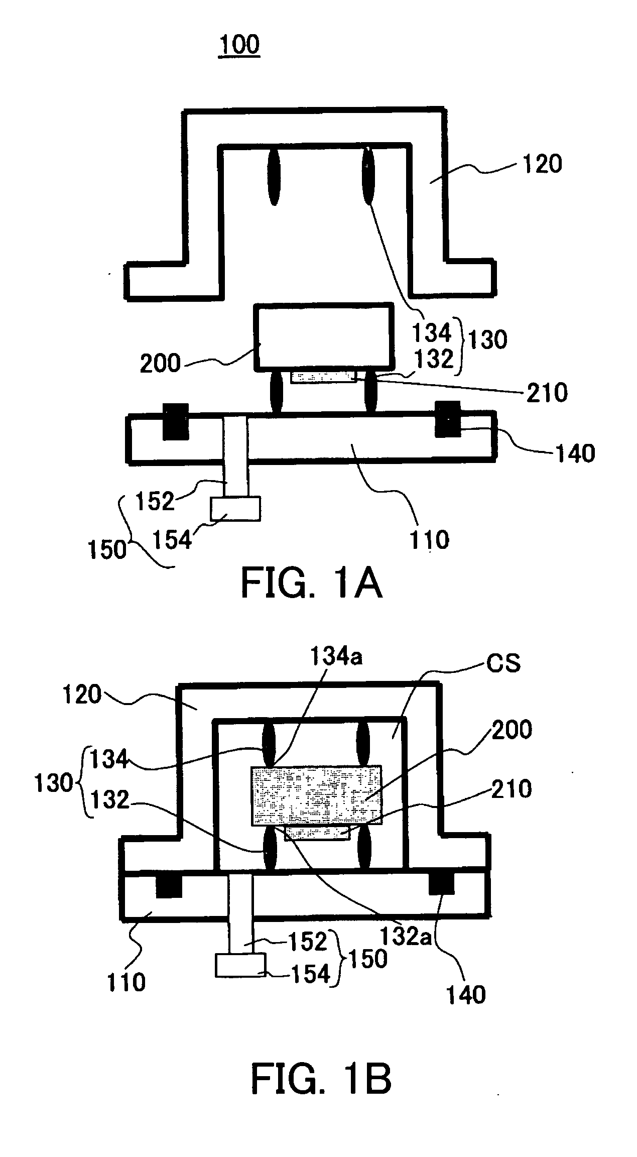
[0031] A description will now be given of a housing unit according to one aspect of the present invention with reference to the accompanying drawings. Like elements in each figure are designated by the same reference numerals, and a duplicate description will be omitted. Here, FIGS. 1A and 1B are schematic sectional views of a structure of the housing unit 100 according to one aspect of the present invention, wherein FIG. 1A shows a state prior to the accommodation of a reticle 200, and FIG. 1B shows a state subsequent to the accommodation of the reticle 200.

[0032] The inventive housing unit 100 is used to feed an object from a first atmosphere to a second atmosphere different from the first atmosphere, and particularly suitable for accommodations of a reticle and wafer in feeding them to an EUV exposure apparatus that includes an exposure chamber maintained in a vacuum atmosphere. In a description of the instant embodiment, the housing unit 100 houses the reticle 200 as an object ...


PUM


Abstract

A housing unit used to feed an object from a first atmosphere to a second atmosphere different from the first atmosphere includes a support member for supporting the object via a contact surface that contacts the object, and an antislip device that prevents slippery of the object relative to the support member.

Description

BACKGROUND OF THE INVENTION [0001] The present invention relates generally to a housing unit, and more particularly to a housing unit that houses a plate, such as a reticle, used for an exposure apparatus that manufactures devices, such as a single crystal substrate for a semiconductor wafer, and a glass substrate for a liquid crystal display (“LCD”). The present invention is suitable, for example, for an exposure apparatus that utilizes an electron beam (“EB”), X-ray, and extreme ultraviolet (“EUV”) light for an exposure light source. [0002] A reduction projection exposure apparatus has been conventionally employed which uses a projection optical system to project a circuit pattern formed on a mask (reticle) onto a wafer, etc. to transfer the circuit pattern, in manufacturing such a fine semiconductor device as a semiconductor memory and a logic circuit in photolithography technology. [0003] The minimum critical dimension to be transferred by the projection exposure apparatus or re...

Claims


Application Information

Patent Timeline
IPC IPC(8): G03B27/62G03F7/20H01L21/027H01L21/673H01L21/68
CPCG03F7/70741G03F7/70808G03F7/7075
Inventor HARA, SHINICHI
Owner CANON KK
Learn More