
Spherical ring antenna

a ring antenna and ring antenna technology, applied in the field of spherical ring antennas, can solve the problems of limited to full size, antennas are sometimes large and impractical for a specific application, and cannot be used in full size, and achieve the effect of enhancing the gain

Inactive Publication Date: 2005-04-28
TECH LICENSING CORP (US)
View PDF11 Cites 11 Cited by
  • Summary
  • Abstract
  • Description
  • Claims
  • Application Information

AI Technical Summary

Benefits of technology

[0007] It is therefore an object of the present invention to provide an antenna that has a shape that enhances its gain relative to its size.
[0008] It is another aspect of the present invention to provide an antenna that is operative for varying its feed impedance and enhancing its gain relative to its size.
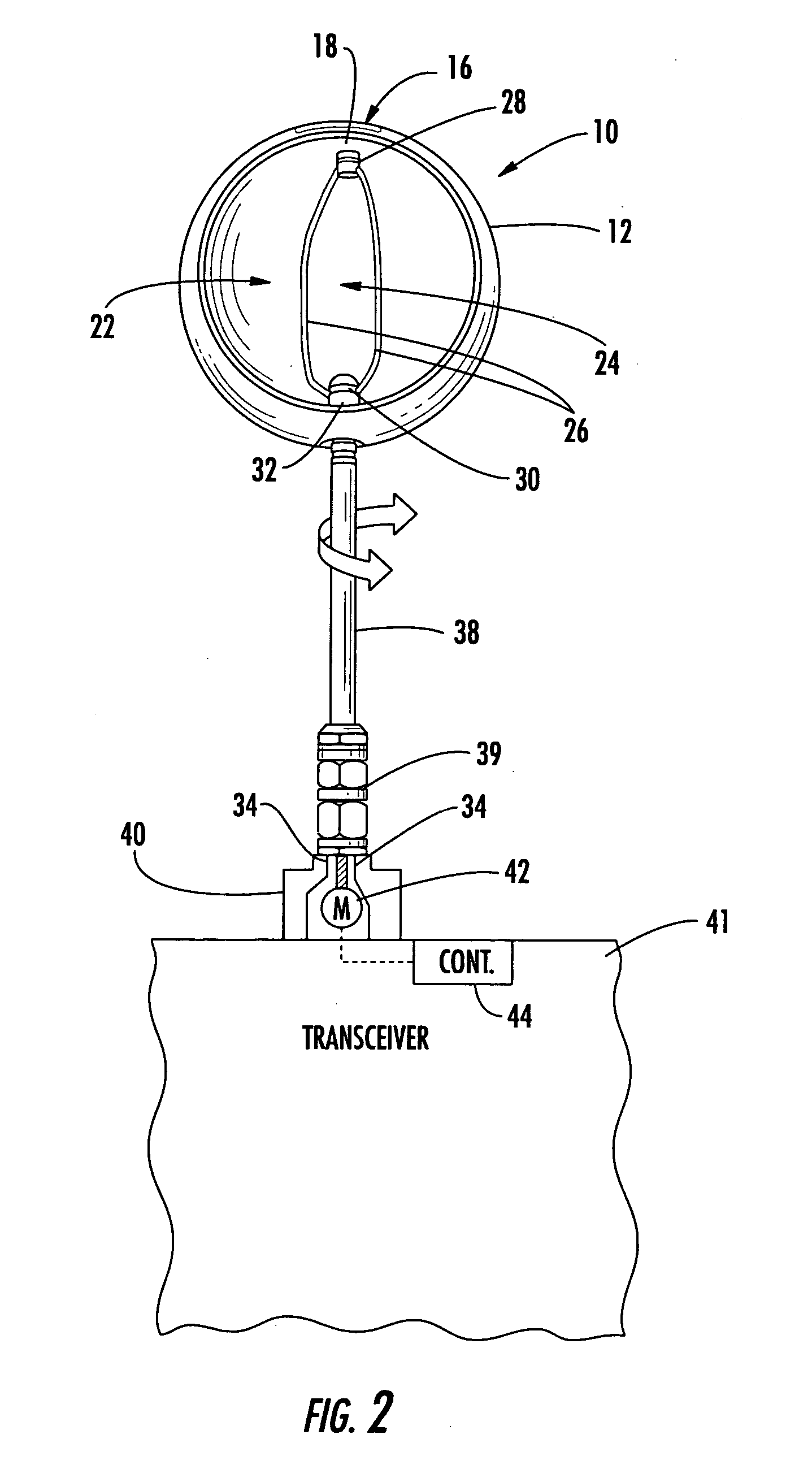
[0009] The present invention advantageously provides an improved antenna that has uniform current distribution throughout its structure and enhances its gain relative to its size. The antenna of the present invention could be used for portable, mobile, and personal communications at many different frequencies, and is especially applicable for use at low frequency ranges up to about 6 GHz, where antennas often can be some of the larger components in the overall design. The antenna of the present invention is a spherical antenna having a maximum surface area with minimum volume. It is self-resonating in one aspect of the invention and is efficient compared to prior art Maxwell and Wheeler antenna designs that traded efficiency for size. The antenna of the present invention can have a forced resonance with high efficiency and could include a variometer for changing the feed impedance. It has uniform current distribution with no Eddy currents and no proximity effect. There is no lost conductor surface between currents and no escaping flux, which makes the antenna of the present invention suitable for medical applications.
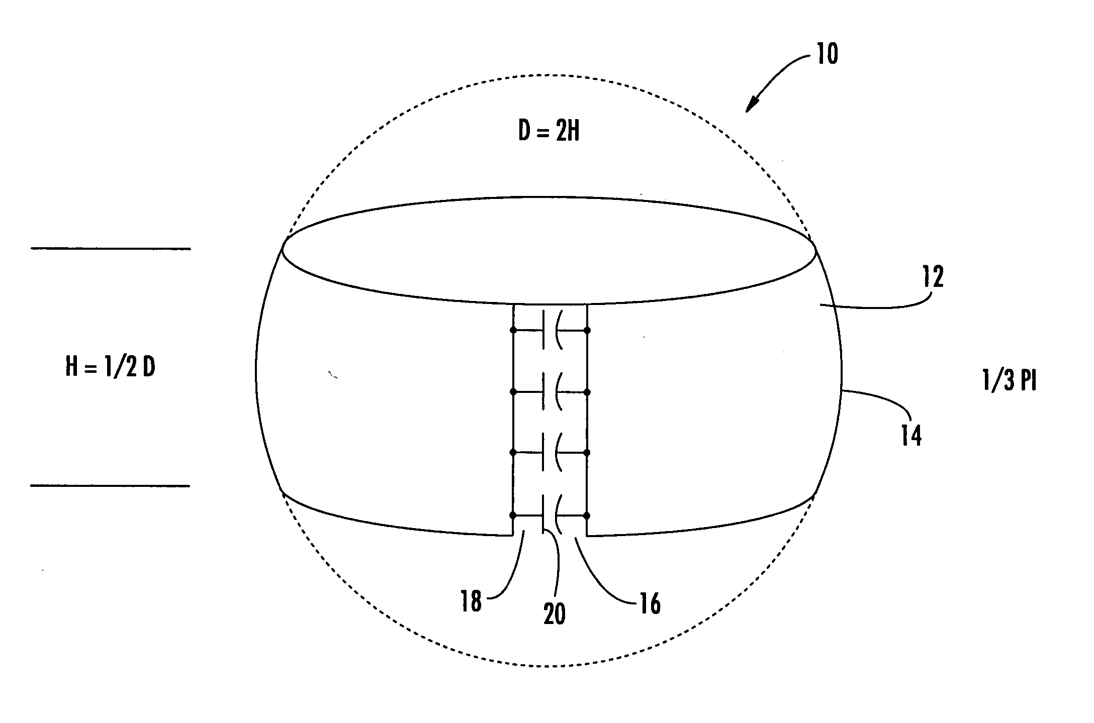
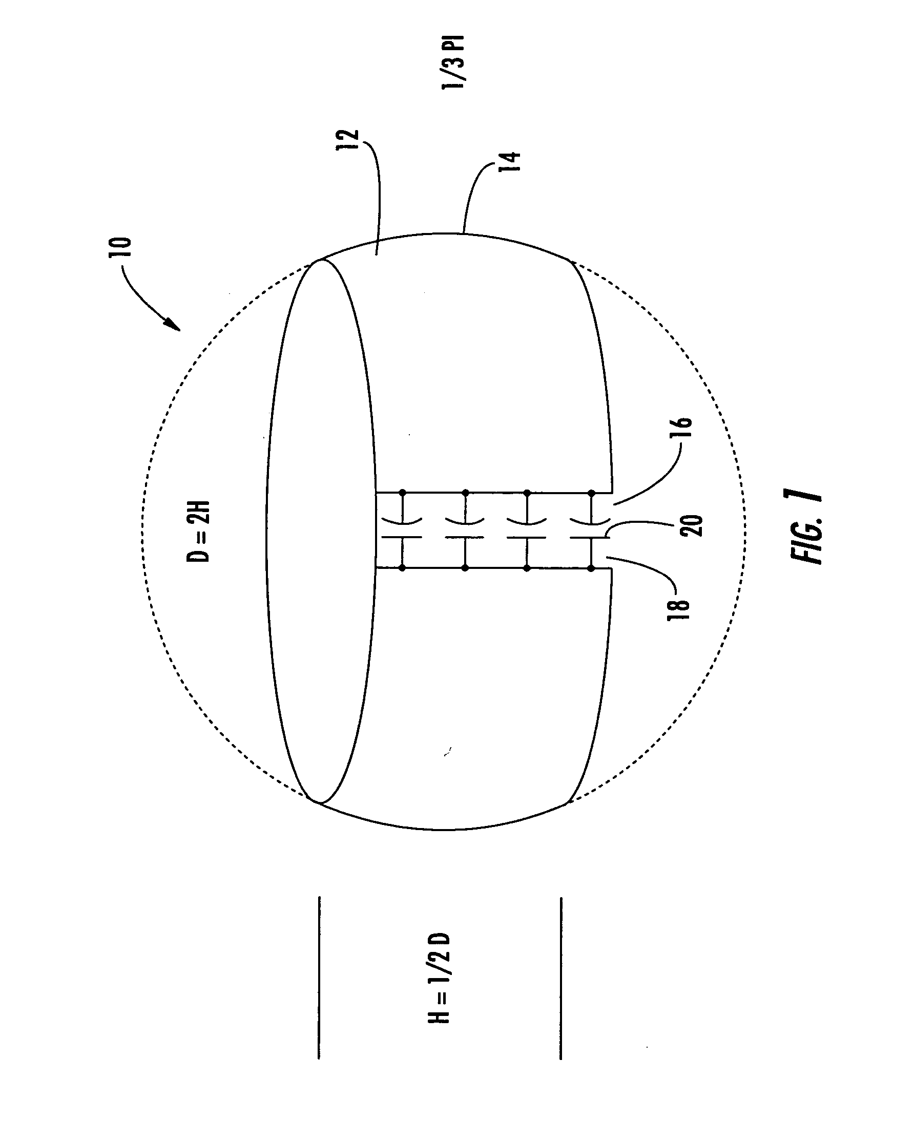
[0010] In one aspect of the present invention, the antenna includes a radiating ring element formed as a spherical sector and having about a one-half wavelength circumference in natural resonance for obtaining uniform current distribution and enhancing its gain relative to its size. The diameter of the radiating ring element is about twice its height in one aspect of the present invention. The spherical sector also comprises a one-third pi sector of a sphere in a suitable embodiment. The radiating ring element can also include a capacitive element formed therein for forcing the radiating ring element to resonance. In one aspect of the present invention a gap is formed within the radiating ring element and is operative as a capacitive element. A capacitor could be mounted within the gap to aid in establishing the desired capacitance for resonance.

Problems solved by technology

Unfortunately, antennas have sizes that are related to wavelength, and they have not been reduced in size at a commensurate level and they increasingly are one of the largest components used in small communications devices.
At very low frequencies, for example, used by submarines or other low frequency communication systems, the antennas become very large, which is unacceptable.
These antennas, however, are sometimes large and impractical for a specific application.
Other antenna designs stressing a small size have used one-half silver wire dipole, but have been limited to full size, self resonant antenna structures.
Two-dimensional antenna designs as inductor / loop antennas have been designed as silver annular rings, but were not practical even though some were small.
Unfortunately, as the turns of wire increased, the additional windings “shaded” the antenna aperture against adjacent turns of the wires and interrupted the field.
Many of these antennas also did not have a uniform current distribution and had Eddy currents distributed throughout the antenna.

Method used


Image

  • Spherical ring antenna
  • Spherical ring antenna
  • Spherical ring antenna

Examples


Embodiment Construction

[0015] The present invention will now be described more fully hereinafter with reference to the accompanying drawings, in which preferred embodiments of the invention are shown. This invention may, however, be embodied in many different forms and should not be construed as limited to the embodiments set forth herein. Rather, these embodiments are provided so that this disclosure will be thorough and complete, and will fully convey the scope of the invention to those skilled in the art. Like numbers refer to like elements throughout, and prime notation is used to indicate similar elements in alternative embodiments.

[0016] The present invention is a small, spherical ring antenna that has a uniform current distribution and enhanced gain relative to its size. The antenna of the present invention is an improvement over prior art antennas that were manufactured to be compatible with miniaturized electronics while attempting to provide high gain for their small size by using basic Maxwell...


PUM


Abstract

An antenna includes a radiating ring element formed as a spherical sector or about a one-half wavelength circumference in natural resonance for obtaining uniform current distribution and enhancing the gain relative to the size of the antenna. A capacitive element, such as a gap, can be formed therein for forcing the radiating ring element to resonance. A variometer feeds the radiating ring element and is operative for varying feed impedance.

Description

FIELD OF THE INVENTION [0001] This invention relates to the field of antennas, and more particularly, this invention relates to electrically small antennas, and to a radiating antenna element that is configured to give the greatest possible efficiency and gain relative to size. BACKGROUND OF THE INVENTION [0002] Newer designs and manufacturing techniques have driven electronic components to small dimensions and miniaturized many communication devices and systems. Unfortunately, antennas have sizes that are related to wavelength, and they have not been reduced in size at a commensurate level and they increasingly are one of the largest components used in small communications devices. In Ultra High Frequency and lower communication applications, antennas size becomes increasingly larger. At very low frequencies, for example, used by submarines or other low frequency communication systems, the antennas become very large, which is unacceptable. It becomes increasingly important in these...

Claims


Application Information

Patent Timeline
Patent Type & Authority Applications(United States)
IPC IPC(8): H01Q1/04H01Q7/00H01Q9/00H01Q9/40
CPCH01Q1/04H01Q9/40H01Q7/00
Inventor PARSCHE, FRANCIS
Owner TECH LICENSING CORP (US)
Learn More