Stronger catalyst using selective washcoat location

Inactive Publication Date: 2005-04-21
DELPHI TECH INC
View PDF5 Cites 2 Cited by
  • Summary
  • Abstract
  • Description
  • Claims
  • Application Information

AI Technical Summary

Benefits of technology

[0007] The present invention provides a strengthened catalytic converter substrate and a method for preparing the substrate using controlled, selective washcoat application to maximize the structural integrity of the thin-walled substrate. The catalytic converter substrate comprises a substrate having cells defined by thin perimeter walls and thin interior walls, and a catalyst washcoat selectively disposed on the substrate so as to maximize substrate strength in those areas requiring the greatest amount of structural integrity.
[0008] The present invention employing selective washcoat application provides the advantage of lower substrate cost as compared to substrates that are strengthened with thicker walls or thicker applied skins. The present invention further provides the advantage of a more robust product design and reduces the amount of fallout due to cracked catalyst.
[0009] The present invention provides the further advantage of reduced processing costs. For example, since there is a high degree of die wear when extruding material such as cordierite, it is desirable to reuse dies for smaller cross-section parts as the outer cells wear out. This is not readily accomplished when wall thickness is different in outer cells versus inner cells. The present invention reduces the need for new extrusion dies by providing added strength to the catalyst where it is needed (e.g., in perimeter cells) without the need for differential wall thickness.
[0010] The present method includes using known coating methods including use of a mask for selectively disposing the washcoat. This provides a further advantage in that tooling costs for washcoat masking are significantly less than the costs of providing substrate walls having different wall thicknesses.

Problems solved by technology

For example, since there is a high degree of die wear when extruding material such as cordierite, it is desirable to reuse dies for smaller cross-section parts as the outer cells wear out.
This is not readily accomplished when wall thickness is different in outer cells versus inner cells.

Method used


Image

  • Stronger catalyst using selective washcoat location
  • Stronger catalyst using selective washcoat location
  • Stronger catalyst using selective washcoat location

Examples


Embodiment Construction

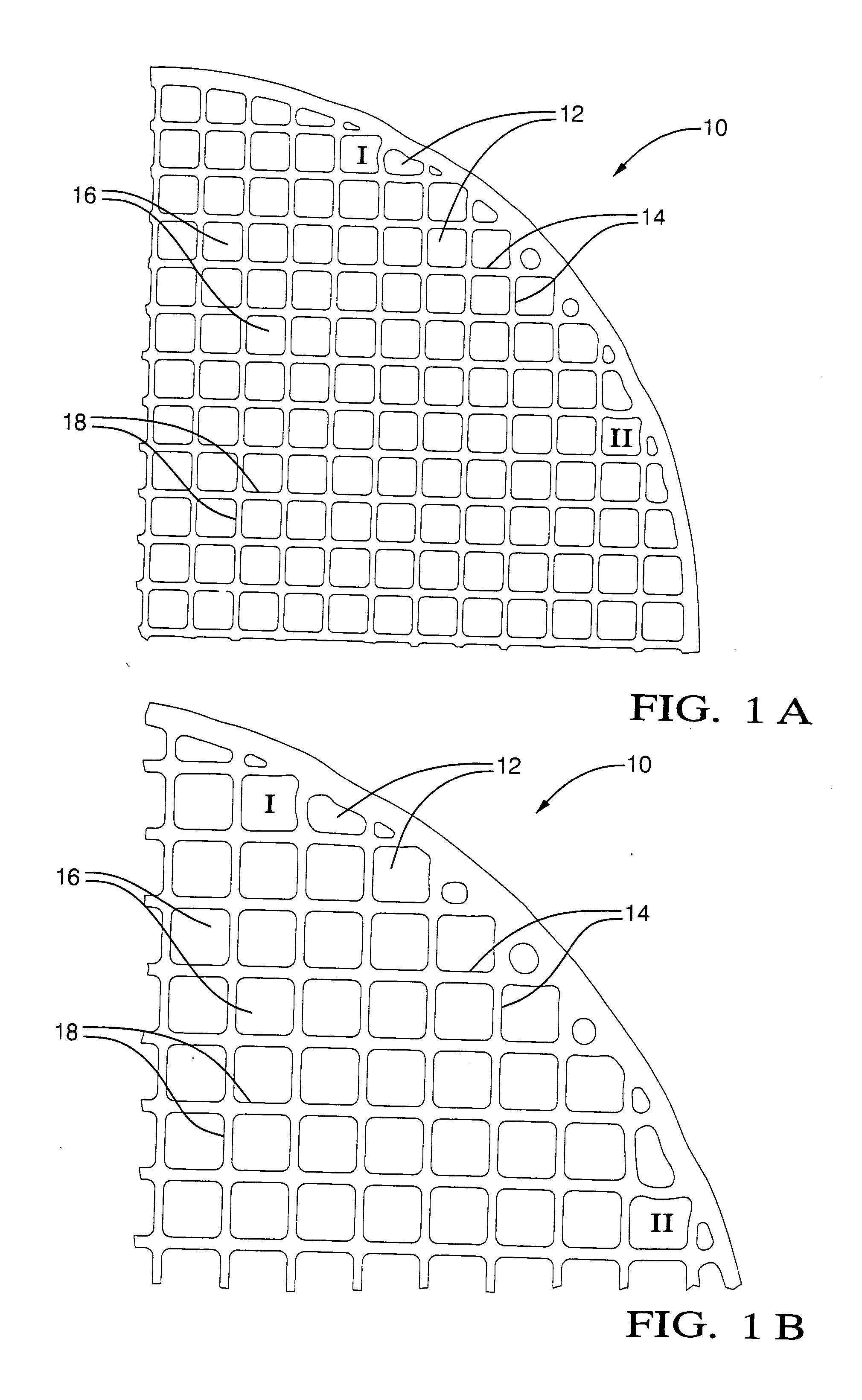
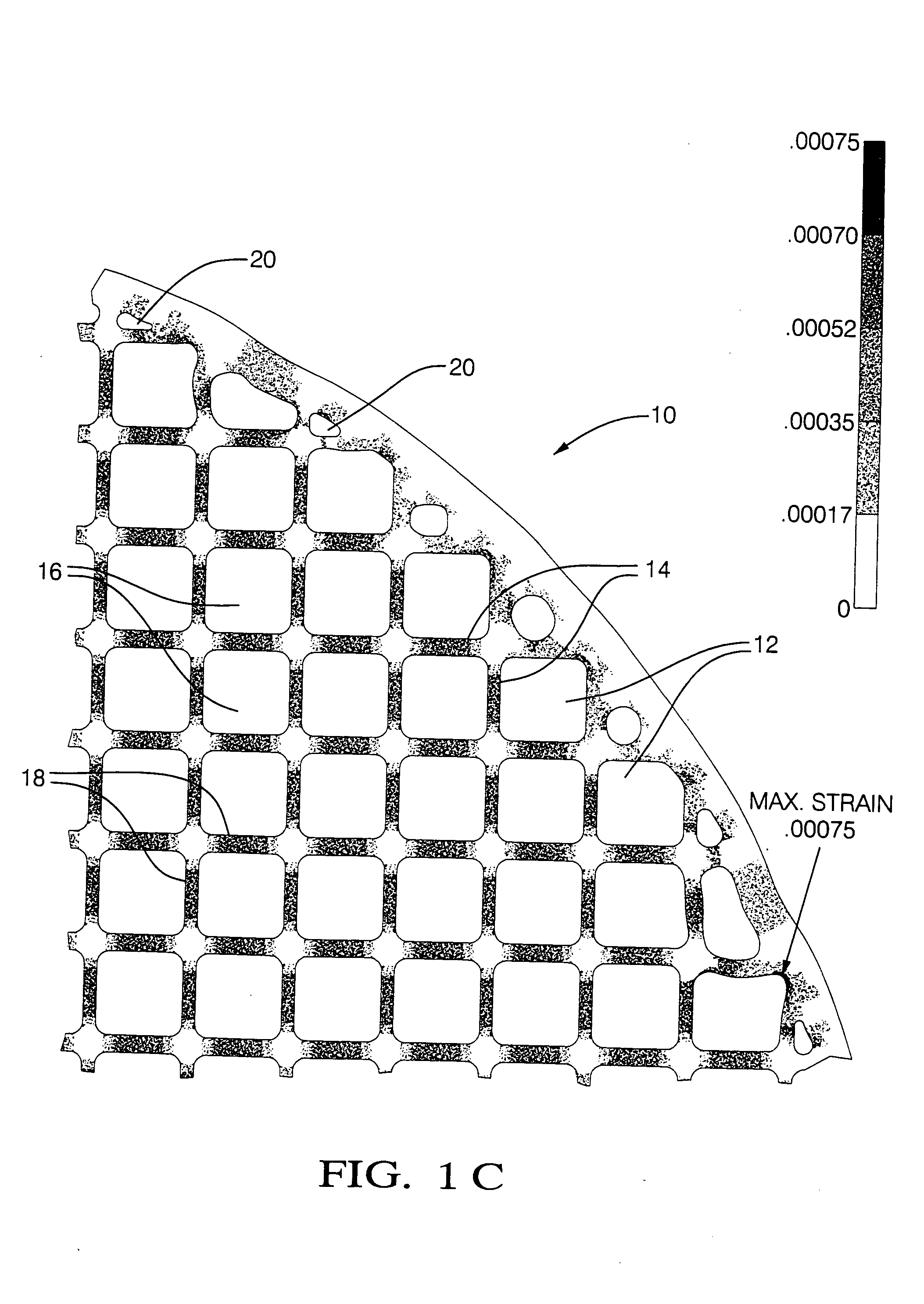
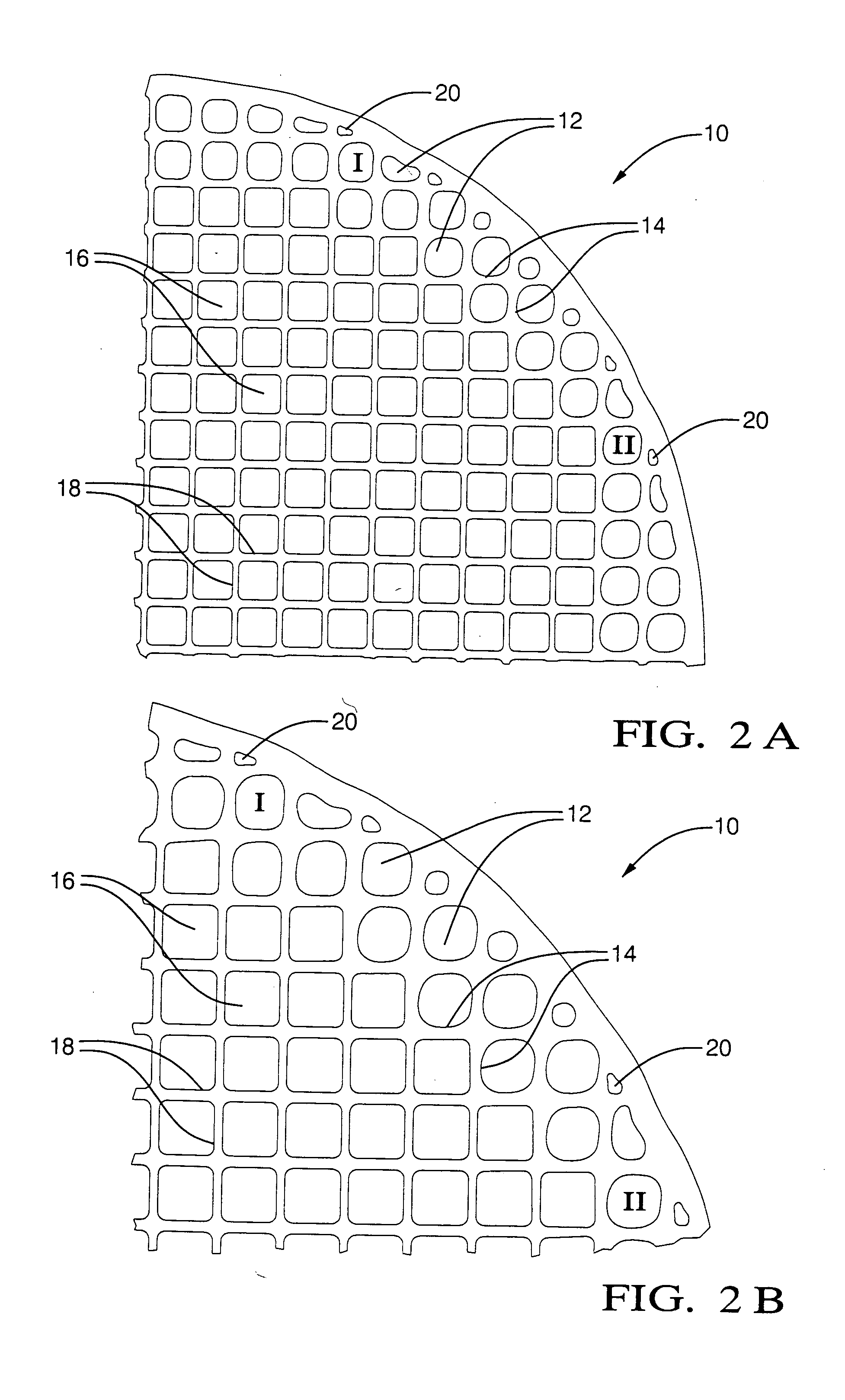
[0021] Turning now to the FIGURES, FIGS. 1A-2C show deformation and tensile strain responses to loads encountered during catalytic converter assembly based on computer modeling tests for thin-walled catalytic converter substrates having uniform washcoats (FIGS. 1A-1C, “non-invention”) and substrates having selective waschcoats in accordance with the present invention (FIGS. 2A-2C, “invention”).

[0022] In FIGS. 1A-1C (non-invention), a partial cross-section of a generally cylindrical thin-walled catalytic converter substrate 10 is shown. A uniform washcoat of about 1 mil is disposed on the substrate 10. FIGS. 2A-2C show a partial cross-section of a generally cylindrical thin-walled catalytic converter substrate 10 prepared in accordance with one possible embodiment of the present invention wherein the substrate 10 is selectively strengthened in the area of perimeter cells 12 by disposing a greater amount of waschcoat on substrate walls in the area of perimeter cells 12.

[0023] Comput...


PUM

PropertyMeasurementUnit
Lengthaaaaaaaaaa
Lengthaaaaaaaaaa
Lengthaaaaaaaaaa

Abstract

A strengthened thin-walled catalytic converter substrate includes thin perimeter walls and thin interior walls defining cells and a catalyst washcoat selectively disposed on the substrate. Washcoat thickness is increased in those cells having the most impact on final catalyst strength, typically the outer cells defined by the perimeter walls. A method for maximizing overall catalyst strength with minimal substrate thermal mass includes selectively applying washcoat based on desired substrate strength and converter assembly method.

Description

[0001] The present invention relates to catalytic converter substrates and more particularly relates to a strengthened catalytic converter substrate and a method for preparing the substrate. BACKGROUND OF THE INVENTION [0002] A variety of ceramic and metal catalytic converter substrates are known. Commercially available ceramic catalytic converter substrates have thin walls (typically about 0.006 inch to about 0.008 inch) and shaped cells, such as round, square, or triangular shaped cells. The substrate is formed by extruding a green ceramic mixture through an extrusion die. The extruded plasticized material is then dried and fired to provide a hard, solid catalytic converter substrate. Any ceramic material having suitable thermal, shock resistance, and melting temperature characteristics, such as cordierite, can be used. A washcoat is applied to the fired substrate, and catalyst solutions are impregnated into the washcoat. To prepare the catalytic converter, the catalyst-coated sub...

Claims


Application Information

Patent Timeline
IPC IPC(8): B01D53/88B01D53/94F01N3/28
CPCB01D53/885F01N3/2828F01N3/28B01D53/94
Inventor MYERS, STEPHEN JOEFOSTER, MICHAEL RALPHLI, FONG Z.
Owner DELPHI TECH INC
Why Eureka
Try Eureka