Three-phase ac generator for vehicle
a technology of alternating current and electric generator, which is applied in the direction of electric generator control, dynamo-electric converter control, and schematic details of the semiconductor/solid-state device, etc., can solve the problems of increasing the number of parts built in the electric generator, difficult to make the connection work, so as to simplify the connection work of each generating coil and each diode pair, and simplify the internal construction of the electric generator.
- Summary
- Abstract
- Description
- Claims
- Application Information
AI Technical Summary
Benefits of technology
Problems solved by technology
Method used
Image
Examples
first embodiment
Entire Explanation of First Embodiment
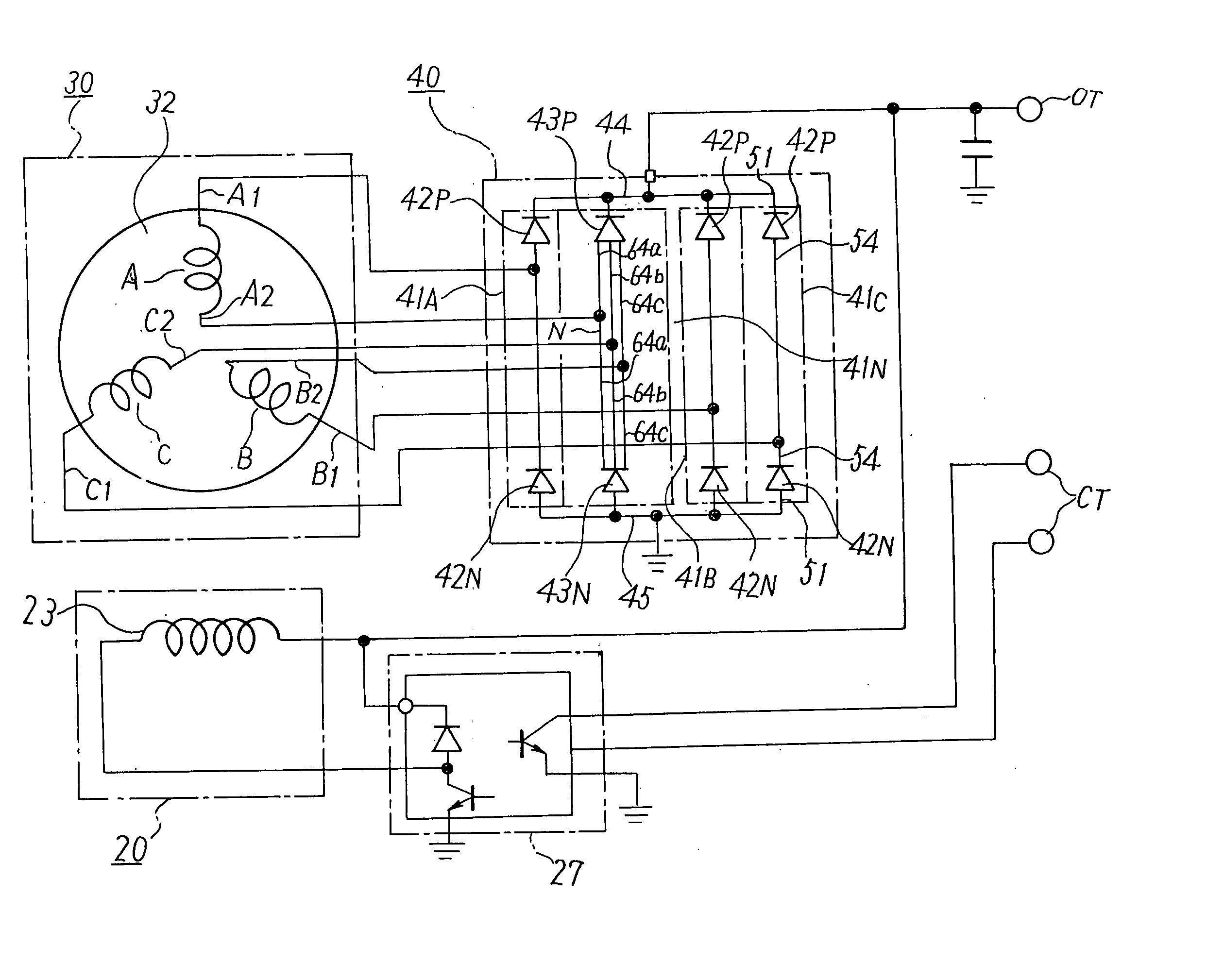
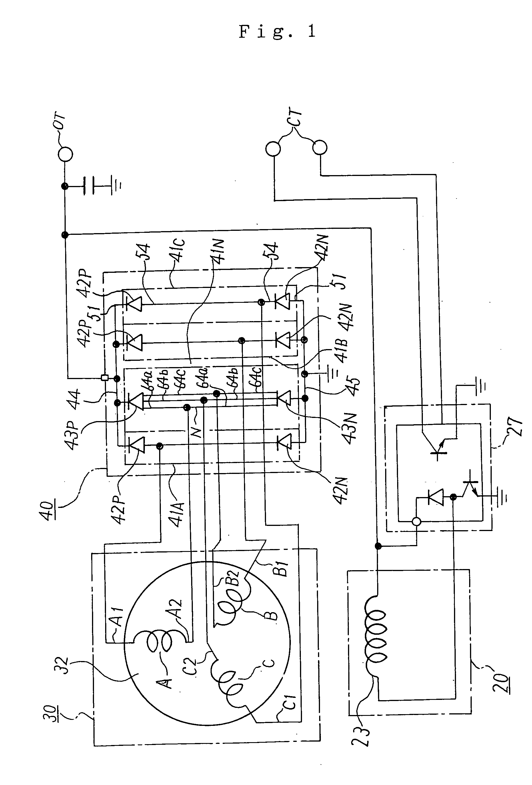
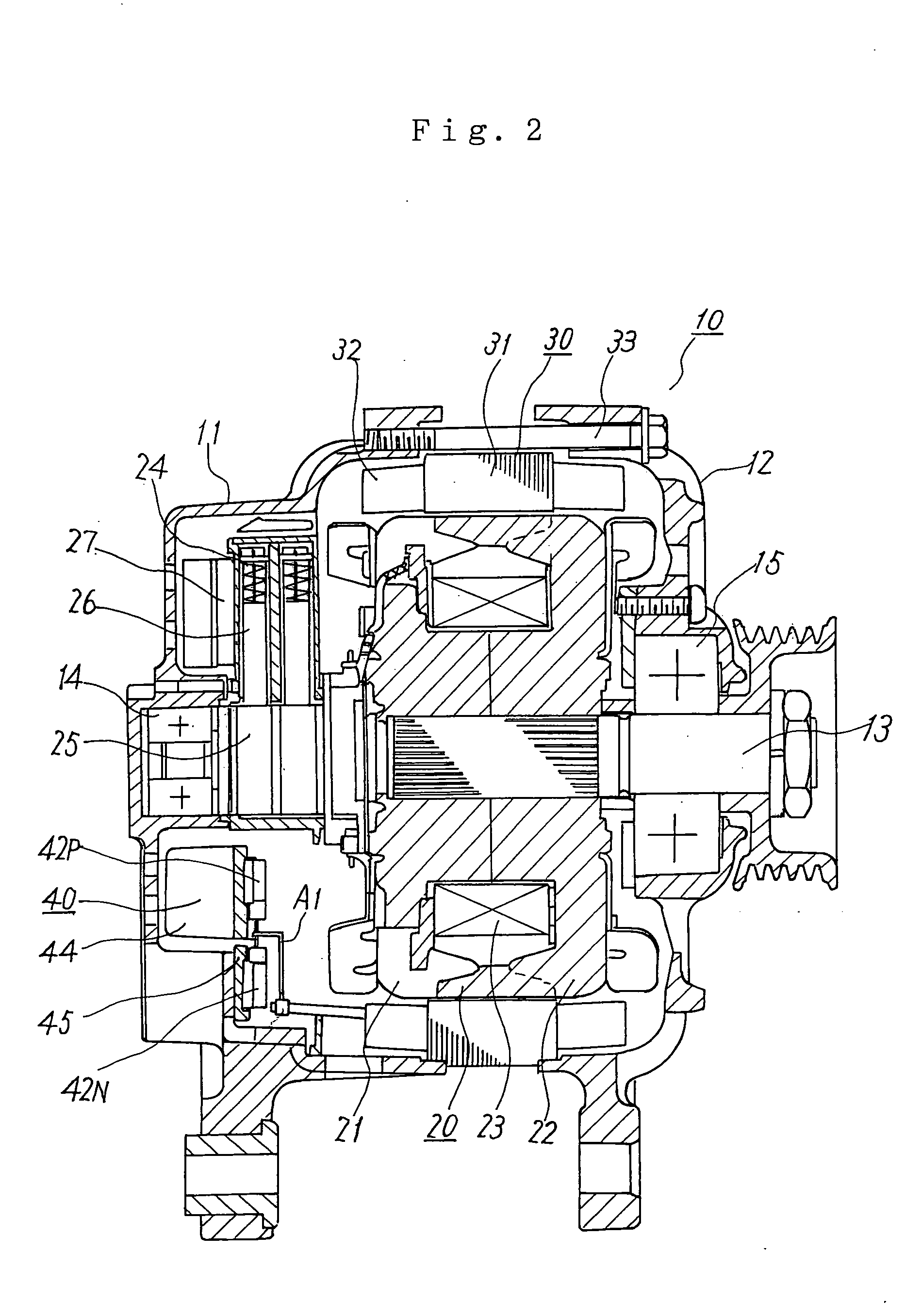
[0035] The three-phase alternating current electric generator 10 for a vehicle shown in FIGS. 1 and 2 is a three-phase alternating current electric generator of a Y-shape connecting type. This three-phase alternating current electric generator 10 has a pair of brackets 11, 12, a rotating shaft 13, a rotor 20, a stator 30 and a rectifier 40. The rotating shaft 13 is rotatably supported by the pair of brackets 11, 12 through ball bearings 14, 15. This rotating shaft 13 is operated by an engine mounted to the vehicle, and the rotor 20 is fixed to this rotating shaft 13.
Explanation of Rotor 20 of First Embodiment
[0036] This rotor 20 is a rotating field magnet and has a pair of field magnet ion cores 21, 22 and a field magnet coil 23. The field magnet coil 23 is magnetized by an unillustrated -battery mounted to the vehicle through an electricity supply mechanism 24. This electricity supply mechanism 24 has a pair of slip rings 25 arranged in the r...
second embodiment
EXPLANATION OF SECOND EMBODIMENT
[0052] In the first embodiment, the package structure 60 shown in FIG. 5 is adopted as the neutral diodes 43P, 43N. However, in the second embodiment, a package structure 60A shown in FIG. 7 is used as the package structure of the neutral diodes 43P, 43N. In this package structure 60A of FIG. 7, first, second and third connecting terminals 64a, 64b, 64c are electrically commonly connected to each other in the exterior of a resin package 63 with respect to the drawing-out terminal 64. The other constructions of the package structure 60A are the same as the package structure 60 of FIG. 5. This package structure 60A of FIG. 7 is also adopted in the neutral diode 43P of the positive side and the neutral diode 43N of the negative side. The anode and the cathode of the diode chip 62 are similarly arranged so as to be reverse to each other in the diodes 43P and 43N.
[0053] In accordance with this second embodiment, the same effects as the first embodiment ca...
third embodiment
EXPLANATION OF THIRD EMBODIMENT
[0054] In this third embodiment, a composite type neutral diode 70 having a package structure shown in FIG. 8 is used instead of the neutral diodes 43P, 43N of the first embodiment. This neutral diode 70 of FIG. 8 is a composite type diode constructed such that the neutral diode 43P of the positive side and the neutral diode 43N of the negative side in the first embodiment are stored into one package. A diode pair 41N for making the neutral point connection is constructed by this one composite type diode 70.
[0055] In this neutral diode 70, two diode chips 72A, 72B and an intermediate electrically conductive substrate 73 are nipped between a pair of electrically conductive substrates 71A, 71B opposed to each other. The intermediate electrically conductive substrate 73 is nipped so as to be located just in an intermediate position of the two diode chips 72A, 72B. The diode chip 72A is a diode chip of the positive side, and is arranged between the electr...
PUM
 Abstract
Description
Claims
Application Information
 - R&D
- Intellectual Property
- Life Sciences
- Materials
- Tech Scout
- Unparalleled Data Quality
- Higher Quality Content
- 60% Fewer Hallucinations
Browse by: Latest US Patents, China's latest patents, Technical Efficacy Thesaurus, Application Domain, Technology Topic, Popular Technical Reports.
© 2025 PatSnap. All rights reserved.Legal|Privacy policy|Modern Slavery Act Transparency Statement|Sitemap|About US| Contact US: help@patsnap.com


