
Medical long object and method for producing the same

a technology of long objects and medical devices, applied in the field of medical long objects, can solve the problems of difficult to provide a lubricating coat, difficult to conduct marking on a curved surface, difficult to provide a desired position mark, etc., and achieve the effect of easy to see and excellent solvent resistan

Inactive Publication Date: 2005-04-14
IWAMI JUN +1
View PDF10 Cites 13 Cited by
  • Summary
  • Abstract
  • Description
  • Claims
  • Application Information

AI Technical Summary

Benefits of technology

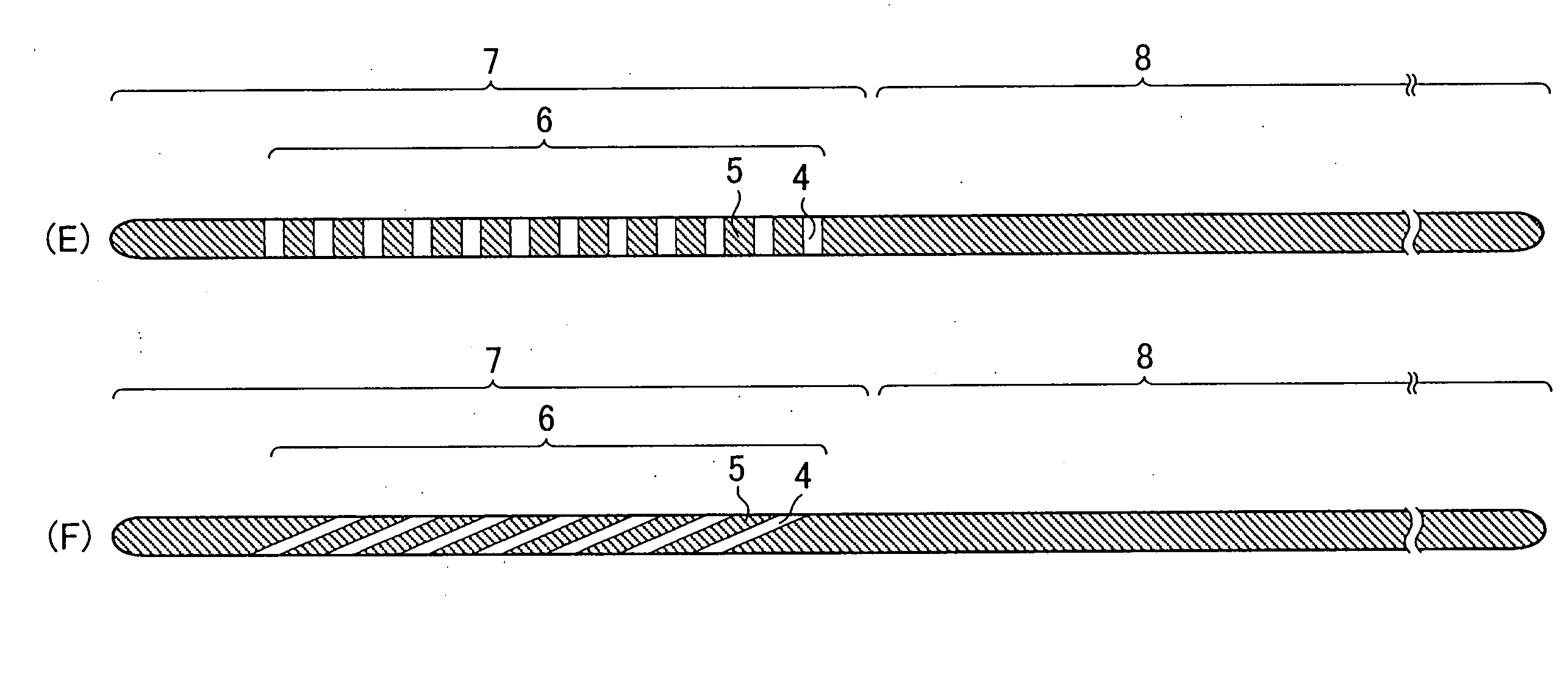
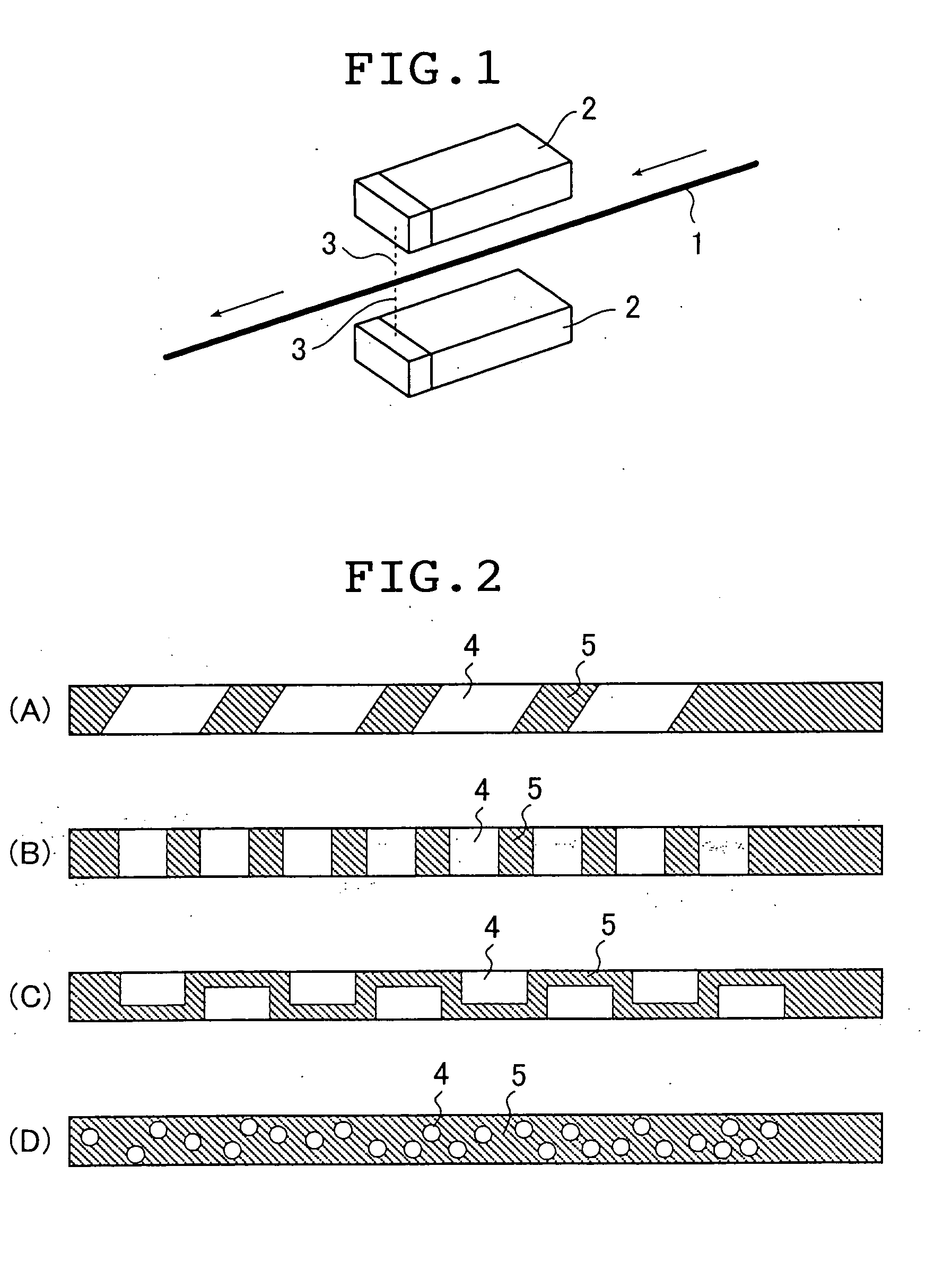
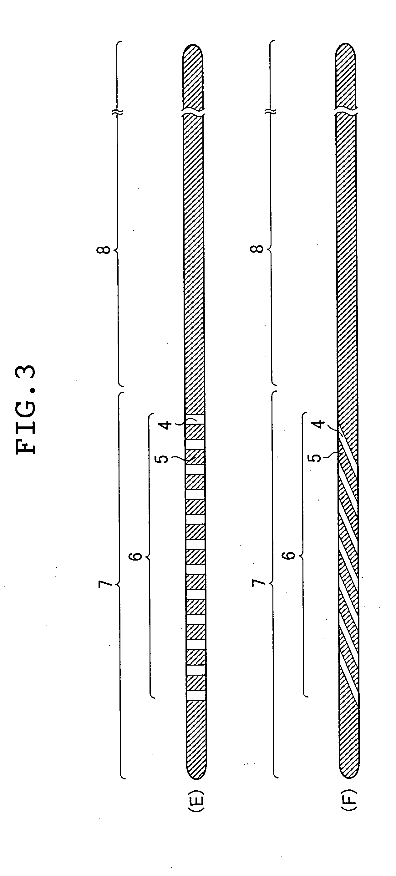
"The present invention provides a medical long object with a mark that is resistant to solvents and can be curved without peeling. The mark is easily visible as it has little raised or recessed. The invention also provides a method for producing the medical long object without the need for drying ink and complicated production processes. The medical long object includes a part formed of a polymeric material containing a laser color developing agent at least in a part of its surface, and a color developing portion formed by color development of the laser color developing agent due to irradiation with laser light. The laser color developing agent contains mica and / or a compound thereof. The invention also provides a method for producing the medical long object by irradiating only a portion of its surface in which a color is to be developed with laser light so as to allow the laser color developing agent to develop a color. The laser color developing agent is preferably contained 0.01 to 10% by mass on the total amount of the polymeric material component."

Problems solved by technology

Therefore, it is difficult to provide a mark at a desired position.
Since ink has no solvent resistance, it is difficult to provide a lubricating coat such as a hydrophilic polymer to the surface of a guide wire after forming a mark.
It is also difficult to conduct marking on a curved surface.
According to this method, a process of drying ink is required, which complicates production processes.
Furthermore, there is a constraint in terms of design that transparent resin can only be used.
Therefore, this method is not preferable.
Therefore, the catheters also have the same problems as those in the guide wires.

Method used


Image

  • Medical long object and method for producing the same
  • Medical long object and method for producing the same
  • Medical long object and method for producing the same

Examples


example 1

[0110] First, 0.2 g of Mica composition 1 and 3 g of a blue pigment were added to 99.8 g of polyurethane resin (ether type), and the mixture thus obtained was kneaded so that Mica composition 1 and the blue pigment were uniformly dispersed in the polyurethane resin.

[0111] Then, a core wire (made of a Ni—Ti alloy, having a diameter of 0.6 mm) was coated with the resultant resin containing a laser color developing agent by extrusion molding so as to have an outer diameter of 0.8 mm, whereby a guide wire was obtained.

[0112] Thereafter, the surface formed of the resin containing a laser color developing agent was irradiated with YAG laser light by a laser light irradiation method shown in FIG. 1, whereby a mark was formed. The movement speed of the guide wire was 300 mm / min., and the energy output of an irradiation origin was 1800 W.

[0113] Furthermore, the surface was coated with a maleic anhydride ethyl ester copolymer by dipping, followed by being dried. Thus, a medical long object...

example 2

[0114] A medical long object (guide wire) of the present invention was obtained by the same method as that of Example 1, except that irradiation with laser light was conducted after coating of a maleic anhydride ethyl ester copolymer in place of conducting coating of a maleic anhydride ethyl ester copolymer after irradiation with laser light.

example 3

[0115] First, 0 to 1 g of Iriodin (laser color developing agent), 30 to 70 g of tungsten, and 0 to 10 g of fluorine powder were added to 30 to 70 g of polyurethane resin respectively, and the mixture thus obtained was kneaded so that these components were uniformly dispersed.

[0116] Then, core wires (made of a Ni—Ti alloy) previously tapered were coated with the resultant resin containing a laser color developing agent by extrusion molding so as to have outer diameters respectively shown in Table 1.

[0117] Each core wire thus obtained was cut in predetermined length and the core wire was coated (hydrophilic polymer coat portion) with a hydrophilic polymer (a maleic anhydride ester copolymer) to a length shown in Table 1 from a tip end portion by dipping. Thereafter, the surface formed of the resin containing a laser color developing agent was irradiated with YAG laser light by the laser light irradiation method shown in FIG. 1, whereby a mark was formed (visual marker portion). The ...


PUM

PropertyMeasurementUnit
particle diameteraaaaaaaaaa

Abstract

A medical long object of the present invention has a part made of a polymeric material containing a laser color developing agent at least in a part of the surface thereof, and a light developing portion formed in the part by color development of the laser color developing agent due to irradiation with laser light.

Description

BACKGROUND OF THE INVENTION [0001] 1. Field of the Invention [0002] The present invention relates to a medical long object having a mark on its surface. [0003] 2. Description of the Related Art [0004] In observation of a biological lumen or the like using an endoscope, in order to guide the endoscope to a predetermined position of the biological lumen or the like, a guide wire is used. The guide wire is inserted to the predetermined position of the biological lumen or the like before guiding the endoscope. [0005] If the guide wire is monochromic, the movement thereof is not recognized even when it is moving in an axial direction. Therefore, it is preferable that a mark representing a position and the like of the guide wire is provided on the surface thereof. [0006] Therefore, conventionally, a method for providing various marks has been proposed. [0007] For example, JP 09-501593 A discloses a method for attaching a hollow tube to a guide wire. According to this method, a hollow tube...

Claims


Application Information

Patent Timeline
Patent Type & Authority Applications(United States)
IPC IPC(8): A61B1/00A61L29/00A61M25/00A61M25/01A61M25/095A61M25/16B41M5/26
CPCA61M25/00A61M25/0009A61M25/0108Y10S430/146A61M2025/006B41M5/267A61M2025/0008
Inventor IWAMI, JUNFUJIMAGARI, HIDEKI
Owner IWAMI JUN
Learn More