
Apparatus and method of multiple antenna transmitter beamforming of high data rate wideband packetized wireless communication signals

a wireless communication signal and antenna beamforming technology, applied in diversity/multi-antenna systems, baseband system details, multi-frequency code systems, etc., can solve the problems of rf energy transmitted between antennas that is destructive and constructive interference, fading in communication channels, and the inability to achieve the effect of reducing the number of antennas

Active Publication Date: 2005-04-14
QUALCOMM INC
View PDF34 Cites 68 Cited by
  • Summary
  • Abstract
  • Description
  • Claims
  • Application Information

AI Technical Summary

Benefits of technology

Channel Effects—Fading and Multipath Communication Channels
For example, a wireless communication system could encounter channel effects, such as transmitting signals across a fading communication channel. The fading in the communication channel may be caused by multipath and propagation loss.
In the case of multipath channel, the RF energy that is transmitted between antennas experience destructive and constructive interference due to multiple paths taken by the RF energy with multiple delays on the way to a receive antenna. Such multipath interference modulates the phase and attenuates the amplitude of signals across all frequencies and carriers used by a wireless communication system. In a WLAN, such multipath interference could cause a receiver to receive a packet in error or to miss a packet entirely.
Antenna diversity is a technique used to deal with fading and multipath communication channels. In a wireless communication system with transmit antenna diversity, a transmitter with multiple antennas, is used to transmit signals.
Prior art diversity trans

Problems solved by technology

802.11a wireless communication systems and other wireless communication systems can experience numerous problems during the transmission of signals.
The fading in the communication channel may be caused by multipath and propagation loss.
In the case of multipath channel, the RF energy that is transmitted between antennas experience destructive and constructive interference due to multiple paths taken by the RF energy with multiple delays on the way to a receive antenna.
Such multipath interference modulates the phase and attenuates the amplitude of signals across all frequencies and carriers used by a wireless communication system.
In a WLAN, such multipath interference could cause a receiver to receive a packet in error or to miss a packet entirely.
The downside of this technique is that it provides slow diversity.
The delay could cause loss in throughput.
Moreover, switching diversity provides limited diversity gain, since only the signal of the selected antenna is used at receiver.
However, the conventional techniques would not work well for wideband signals that have transmitted phase and power that are not constant over the transmitted signal bandwidth and that are frequency dependent, such as 802.11a signals.
Therefore, conventional antenna diversity techniques are not applicable to wideband signal wireless communication signals, such as 802.11a signals.
Conventional antenna beamforming can not efficiently work for mobile nodes, since the beam can be focused in the wrong direction if the mobile nodes move.
In addition environmental effects, such as movement of objects can change the communication channel between the beamforming transmit antennas and the receiver, therefore causing loss of connection.
However, the conventional techniques would not work well for wideband signals that have transmitted phase and power that are not constant over the transmitted signal bandwidth and that are frequency dependent, such as 802.11a signals.

Method used


Image

  • Apparatus and method of multiple antenna transmitter beamforming of high data rate wideband packetized wireless communication signals
  • Apparatus and method of multiple antenna transmitter beamforming of high data rate wideband packetized wireless communication signals
  • Apparatus and method of multiple antenna transmitter beamforming of high data rate wideband packetized wireless communication signals

Examples


Embodiment Construction

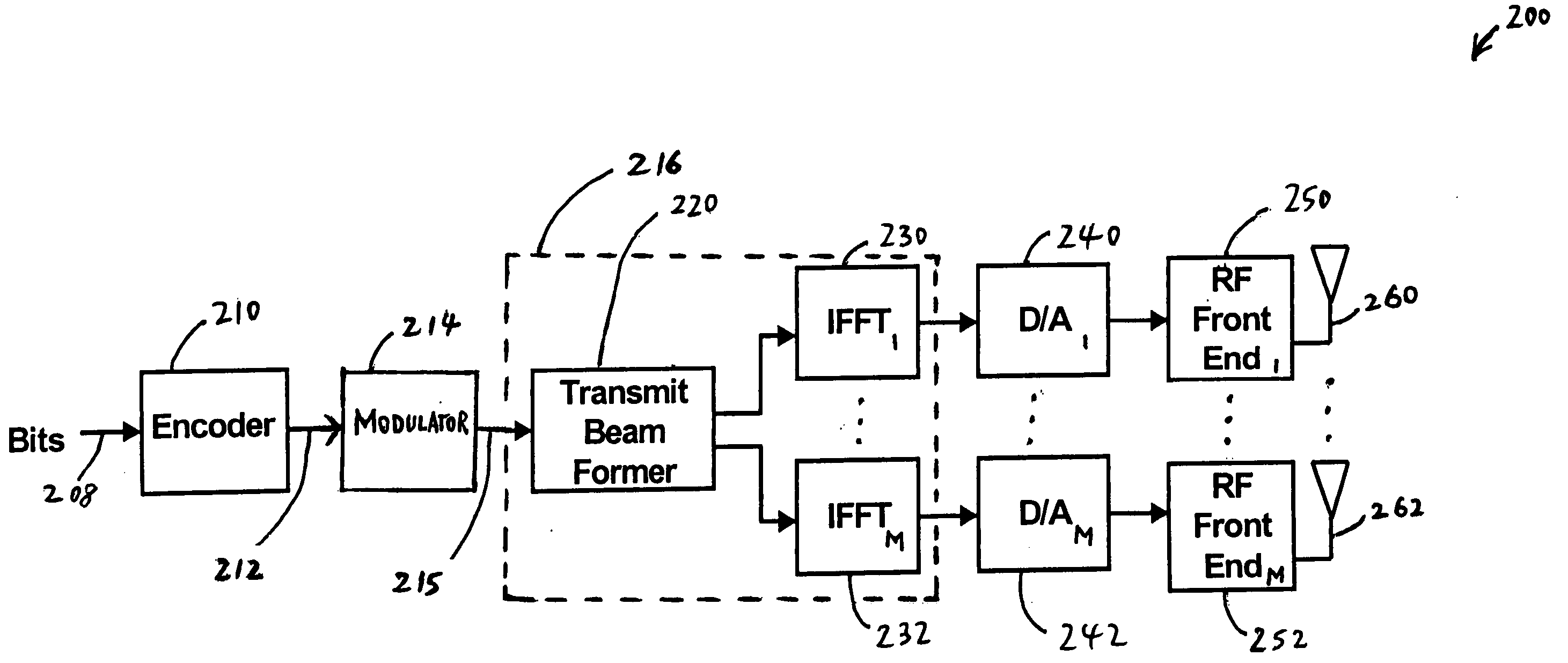
The present invention provides a system and method of multiple antenna transmitter beamforming of high data rate wideband wireless communication signals in a wideband wireless communication network. Referring to FIG. 2, in an exemplary embodiment having two transmit chains, the present invention provides a multiple antenna transmitter beamformer 216 that includes a transmit beamformer 220 and M Inverse Fast Fourier Transform units (IFFTs) 230, 232, logically interconnected as shown. While M is shown as equal to 2 in FIG. 2, M can be an integer greater than or equal to 2. In an exemplary embodiment, high data rate wideband wireless communication signals are packetized OFDM signals, and may be mobile, such as with a driver in a moving vehicle, or movable, such as movement within the confines of a building. To the extent that mobility is discussed herein, reference will be made to mobile, although it will be understood that this applies also to movable. In an exemplary embodiment, the...


PUM


Abstract

The present invention provides an apparatus and method of multiple antenna transmitter beamforming of high data rate wideband packetized wireless communication signals, where each of the signals comprises N frequencies, where N is a positive integer. The apparatus, in an exemplary embodiment, includes (1) a transmit beamformer that co-phases and weights the signals for each of the N frequencies across M antennas, thereby generating M co-phased and weighted frequency data and (2) M Inverse Fast Fourier Transform units (IFFTs) that convert the M co-phased and weighted frequency data into M digital outputs, and M transmit antennas transmitting the M co-phased and weighted signals, where M is an integer greater than or equal to 2.

Description

FIELD OF THE INVENTION The present invention relates to wireless communications. More particularly, the invention relates to an apparatus and method of multiple antenna transmitter beamforming of high data rate wideband packetized wireless communication signals. BACKGROUND OF THE INVENTION Wireless communication systems use antennas to communicate signals. A wireless local area network (WLAN) is a type of wireless communication system that communicates information between nodes in a given area. Wireless communication systems use transmitters to transmit signals. Types of Signals Narrowband and Wideband Signals Most current wireless communication systems are narrowband signal systems. Narrowband signals have signal bandwidths ranging from tens of kilohertz (kHz) (e.g. 50 kHz) to hundreds of kilohertz (500 Khz). In contrast, wideband, or broadband, signals have signal bandwidths greater than 1 MHz. 802.11 and 802.11a One type of wideband signal is the signal used in WLANs usin...

Claims


Application Information

Patent Timeline
IPC IPC(8): H04B7/06H04L25/02H04L27/26
CPCH04B7/0617H04L25/0206H04L27/2614H04L27/2626H04L27/2608H04L5/0044H04L25/0204
Inventor CHOI, WON-JOONTEHRANI, ARDAVAN M.GILBERT, JEFFREY M.NG, SAMUEL
Owner QUALCOMM INC
Learn More