
Method of channel allocation for a mobile terminal moving in a cellular communication network

a mobile terminal and channel allocation technology, applied in the field of channel allocation for mobile terminals moving in cellular communication networks, can solve the problems of slow moving mobiles that may require frequent inter-cell handovers, inability to decode neighbor cell sch data, and inability to accurately predict the handover of neighbor cells, so as to reduce the number of neighbor cell sch decoding and signal level measurement, the effect of improving communication network performance in connection with handovers in cellular network layouts

Inactive Publication Date: 2005-04-07
NOKIA CORP
View PDF6 Cites 92 Cited by
  • Summary
  • Abstract
  • Description
  • Claims
  • Application Information

AI Technical Summary

Benefits of technology

[0054] Advantageously, with the present invention implemented, delays in neighbor cell SCH decoding and signal level measurement are significantly reduced and may thus no longer result in incomplete data for inter-cell handover decision or even unsuccessful handovers. Hence, communication network performance in particular in connection with handovers in a cellular network layouts is improved.
[0055] Thus, a continuous call connection even for fast moving mobile terminals in cellular network layouts (microcell and / or macrocell) due to successful handovers is enabled, while involving only a slight reduction of speech quality on half rate and / or quarter rate transmission channels assigned to the moving terminals as compared to full rate channels.
[0056] Still further, a mobile terminal may perform more frequently signal level measurements concerning neighbor base stations, i.e. base stations of cells surrounding the current cell in which the mobile terminal is located. A rather rapid acquisition of signal level data and SCH data from new neighbor cells is enabled by more frequent measurements, which in turn results in a low delay experienced by a base station controller BSC receiving measurement data concerning new neighbor cells after an inter-cell handover occurred.
[0057] Also, the method of the present invention may easily be implemented to the control algorithms at the base station controller, while no modifications to the protocols or the base station subsystem BSS and / or radio access network RAN are required.

Problems solved by technology

This change of channels might be required as caused by the movement of an active terminal (crossing a cell boundary) or caused by spectrum, user profile, capacity or network management issues.
However, as the relative phases of TCH and control channel multiframes are random, in the worst case on a FR channel, one must attempt SCH decoding 11 times before it may be performed successful.
Thus, as set out above, in GSM / EDGE cellular networks there is a delay in decoding the SCH data from a new neighbor cell.
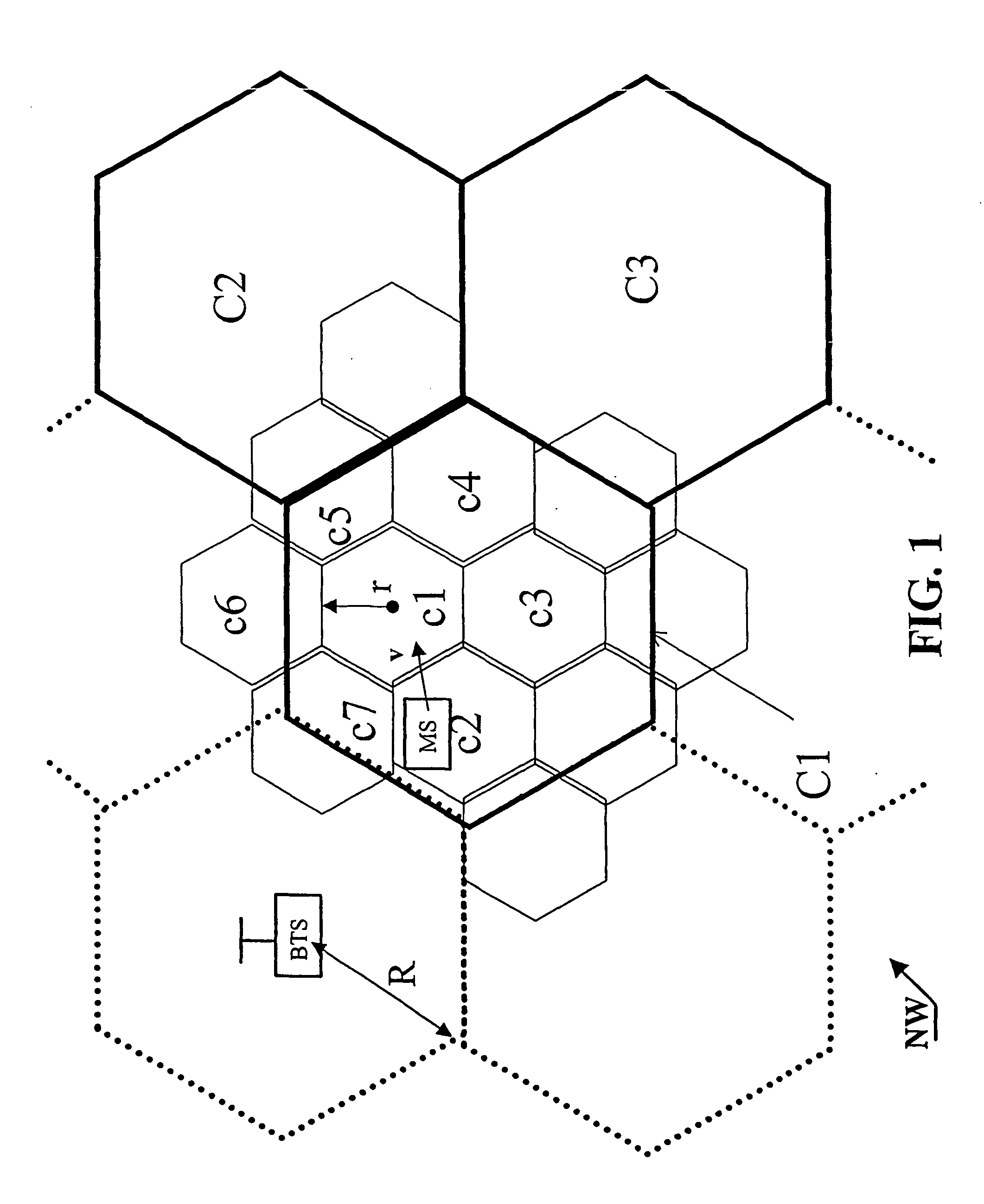
In cellular networks adopting e.g. a microcell network arrangement, fast moving mobiles may require frequent inter-cell handovers due to frequent cell border crossings.
Assuming further that 6 neighbor base stations are to be monitored, 6*1.32 s=7.92 s were required for decoding / measuring the SCH of the neighbor BS which, being about half the time the mobile terminal needs for traveling, is quite too long for taking a decision concerning handover Such delays in neighbor cell SCH decoding and level measurement may thus result in incomplete data for inter-cell handover decision or even unsuccessfull handovers.
This, however, is not a feasible solution in networks or areas, where only the microcell network layout exists (cells denoted with lowercase letter in FIG. 1).

Method used


Image

  • Method of channel allocation for a mobile terminal moving in a cellular communication network
  • Method of channel allocation for a mobile terminal moving in a cellular communication network
  • Method of channel allocation for a mobile terminal moving in a cellular communication network

Examples


Embodiment Construction

[0066] The present invention will now be described in detail with reference to the accompanying drawings.

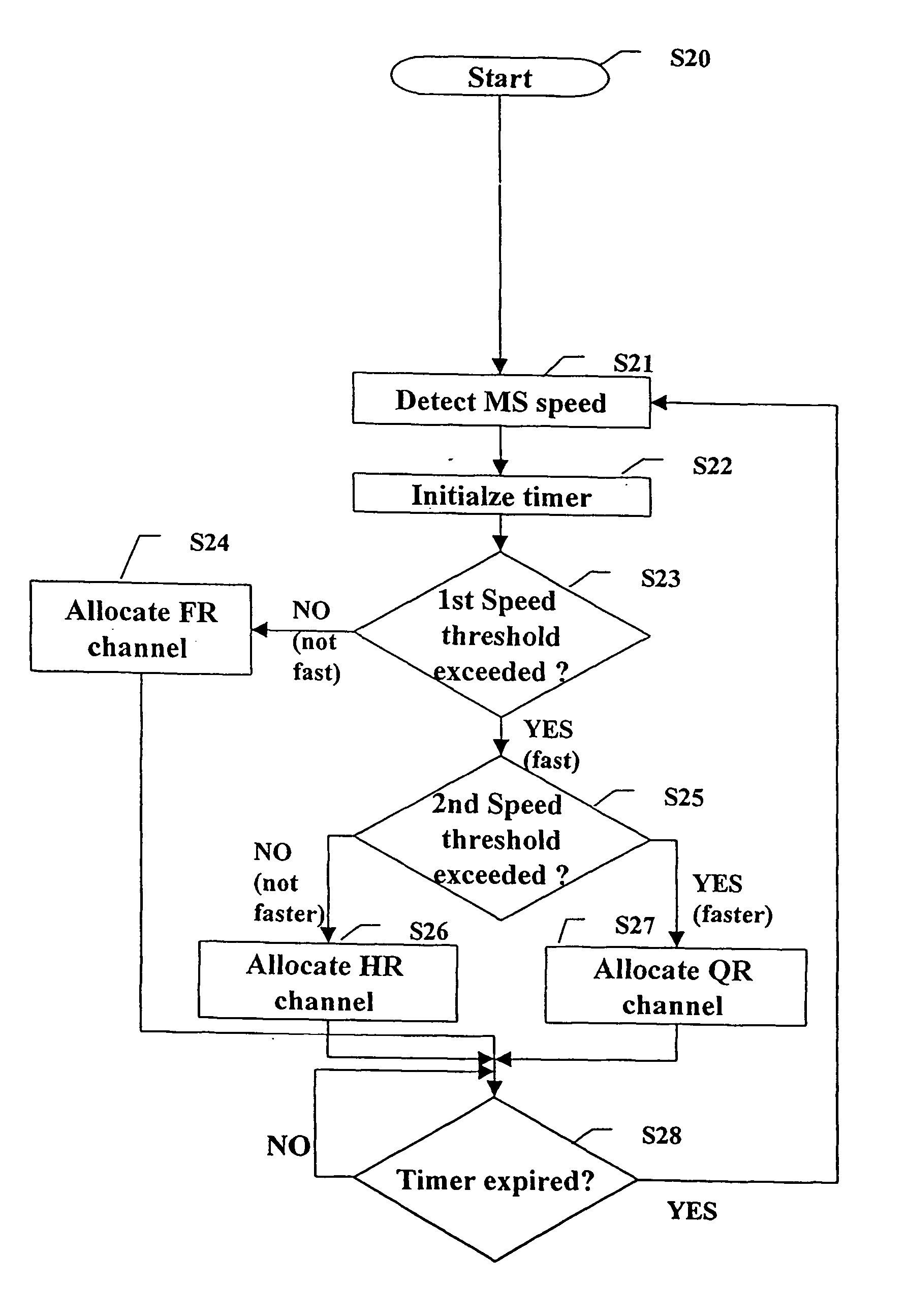
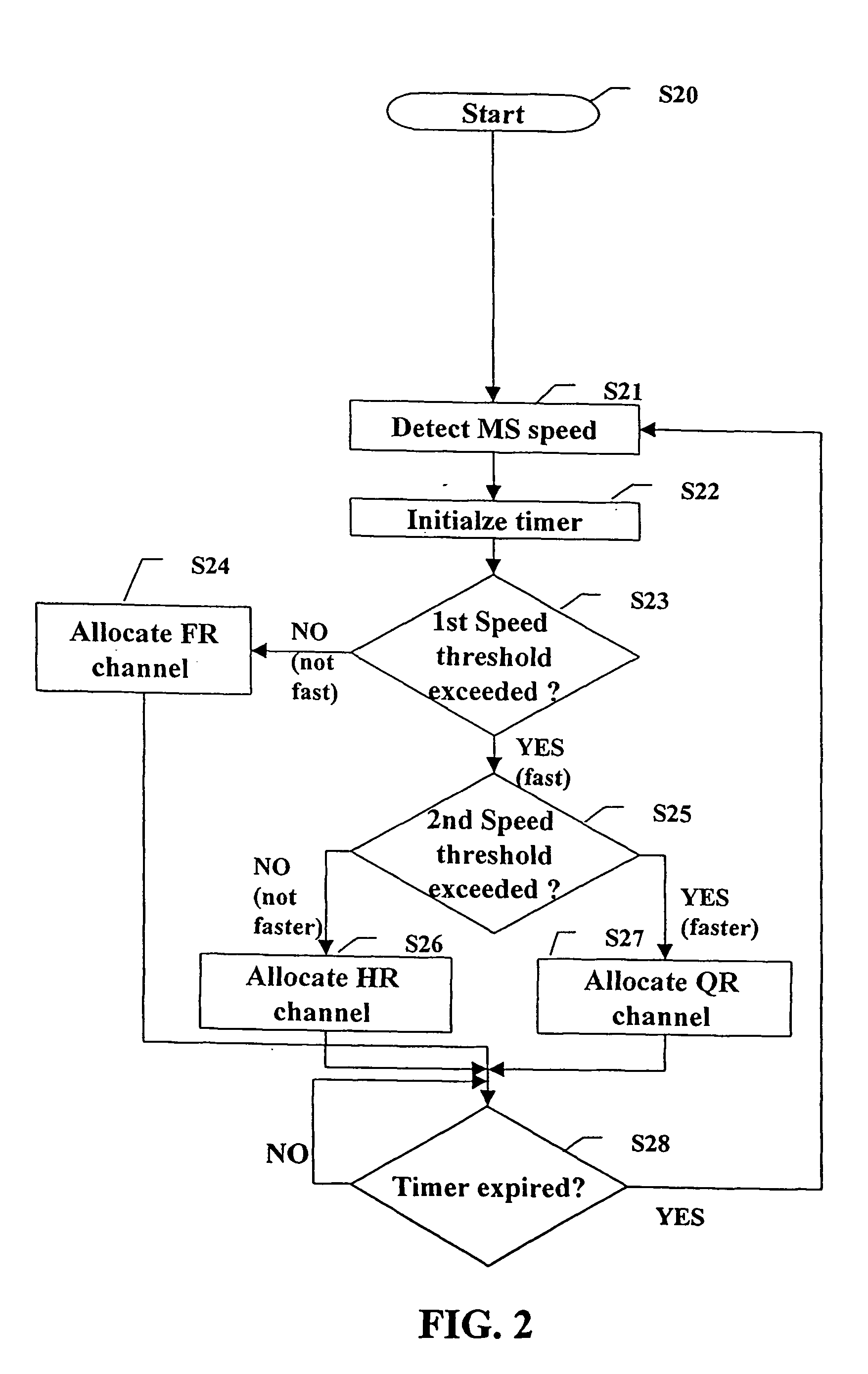
[0067] As stated above, for a mobile terminal MS moving in a cellular communication network NW, channel allocation is performed such that the speed v of said mobile terminal MS moving in said network is detected, and dependent on said detected speed v a channel of a specific type is allocated to said mobile terminal MS.

[0068] This means that in a cellular network, if the speed of the mobile terminal exceeds a specific speed threshold, moving mobile terminals are considered to be “fast” moving terminals and are assigned a half rate HR or quarter rate QR speech channel. Thus, the proportion of idle frames as compared to a full rate FR channel is increased. This will greatly increase the speed at which synchronization channel SCH data from neighboring cells (contained in 51-multiframes) can be decoded. This, in turn will reduce the minimum interval between successive inter-cell ha...


PUM


Abstract

The present invention proposes a method of channel allocation for a mobile terminal (MS) moving in a cellular communication network (NW), said method comprising the steps of: detecting (S21) the speed of said mobile terminal (MS) moving in said network, and dependent on said detected speed (S23, S25), allocating (S24, S26, S27) a channel of a specific type to said mobile terminal (MS). Accordingly, with the present invention implemented, delays in neighbor cell SCH decoding and signal level measurement are significantly reduced and may thus no longer result in incomplete data for inter-cell handover decision or even unsuccessfull handovers. Hence, communication network performance in particular in connection with handovers in a cellular network layout is improved. The present invention also concerns an accordingly adapted device for channel allocation.

Description

FIELD OF THE INVENTION [0001] The present invention relates to a method of channel allocation for a mobile terminal moving in a cellular communication network. BACKGROUND OF THE INVENTION [0002] Cellular communication networks such as the GSM network system have widely spread in recent years with the increase of the demand for mobile communication. [0003]FIG. 1 shows a rough outline of a part of a cellular communication network. Generally, the network area served by the network is composed of individual cells C1, C2, C3 . . . , and / or c1, . . . c7. Each cell in turn is served by a respective base station BS or base transceiver station BTS (not shown in every cell). The coverage area of such a base station BS is defined by the cell radius R and / or r. The coverage area and cell radius are adjustable by the transmit power used by the transmitter of the base station BTS. [0004] Thus, dependent on the transmit power of the BTS used, the network may be composed of so-called macrocells mea...

Claims


Application Information

Patent Timeline
IPC IPC(8): H04L1/00H04W36/18
CPCH04L1/0002H04L1/0015H04W24/10Y02B60/31H04W36/18H04W64/006H04W72/04H04W36/08Y02D30/50H04W36/00692
Inventor POSTI, HARRIPELTOLA, JUKKA
Owner NOKIA CORP
Learn More