
Method and system for active purging of pellice volumes

a technology of pellice and purging volume, applied in the field of pellice purging, can solve the problems of reducing productivity, affecting the purging effect, so as to achieve the effect of minimizing the stress on the pelli

Inactive Publication Date: 2005-04-07
ASML HLDG NV
View PDF11 Cites 12 Cited by
  • Summary
  • Abstract
  • Description
  • Claims
  • Application Information

AI Technical Summary

Benefits of technology

The present invention provides methods and systems for fast purging of pellicle volumes. A purge device is provided for actively purging a pellicle-pellicle assembly. The device includes a base with a cavity, a purge gas input interface, and a purge gas output interface. A reticle-pellicle assembly is placed in the cavity, with a narrow gap region between the reticle and the pellicle. The purge device uses a high pressure in the first region to purge the pellicle volume. The purge gas flows through the narrow gap region and the gap region under the pellicle surface. The purge device also includes a pressure balancing plate and flow resistant plates to control the pressure and flow of the purging gas. The technical effects of the invention include faster purging of pellicle volumes, improved purity of the purging gas, and minimized stress on the pellicle.

Problems solved by technology

Such passive gas diffusion, however, takes a long time to achieve a required gas concentration and purity in the pellicle volume.
Active purging, where gas is directed to a pellicle volume, has been done at low pressure levels which takes a relatively long time to purge a given volume.
Such delay reduces productivity and increases the overall lithographic manufacturing process time.
As a result, many pellicles are vulnerable to stress—especially due to a displacement force on a plane of the pellicle.
Fast purging of a pellicle volume at high pressure can exert excessive stress on a pellicle causing damage and possibly rupture.
This problem even limits fast purging of flexible pellicles since they may be stretched and unable to return to their original shape.
Fast purging is made even more difficult by the poor permeability of many pellicle frames.
Impermeability to gas makes solid pellicle frames unsuited for applications where a pellicle volume must be purged.
Such gas-permeable pellicle frames are still somewhat restrictive to purging flows, since the material must also act as a particle barrier.

Method used


Image

  • Method and system for active purging of pellice volumes
  • Method and system for active purging of pellice volumes
  • Method and system for active purging of pellice volumes

Examples


example environment

[0034] Example Environment

[0035] The present invention can be used in any type of photolithographic system including, but not limited to, ultra-violet (UV) lithographic systems having an exposure wavelength of 157 nanometers (nm) or less. The present invention is not intended to be limited to UV lithographic systems and indeed can be used in other lithographic systems having exposure wavelengths greater or smaller than ultraviolet wavelengths as would be apparent to a person skilled in the art given this description. Further, the present invention is described with respect to fast purging; however, the present invention can be used in a passive purge process or slower active purge process, as desired in a particular application.
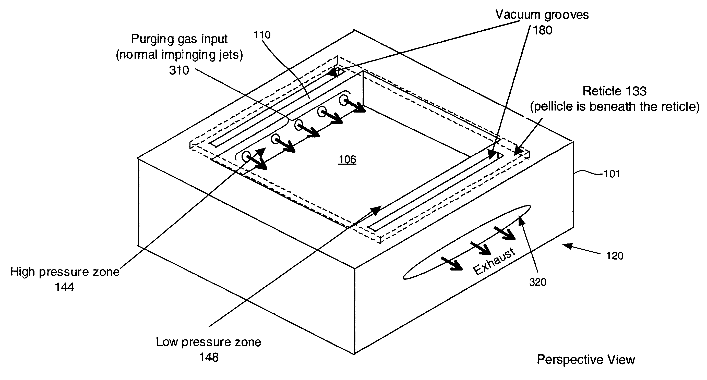
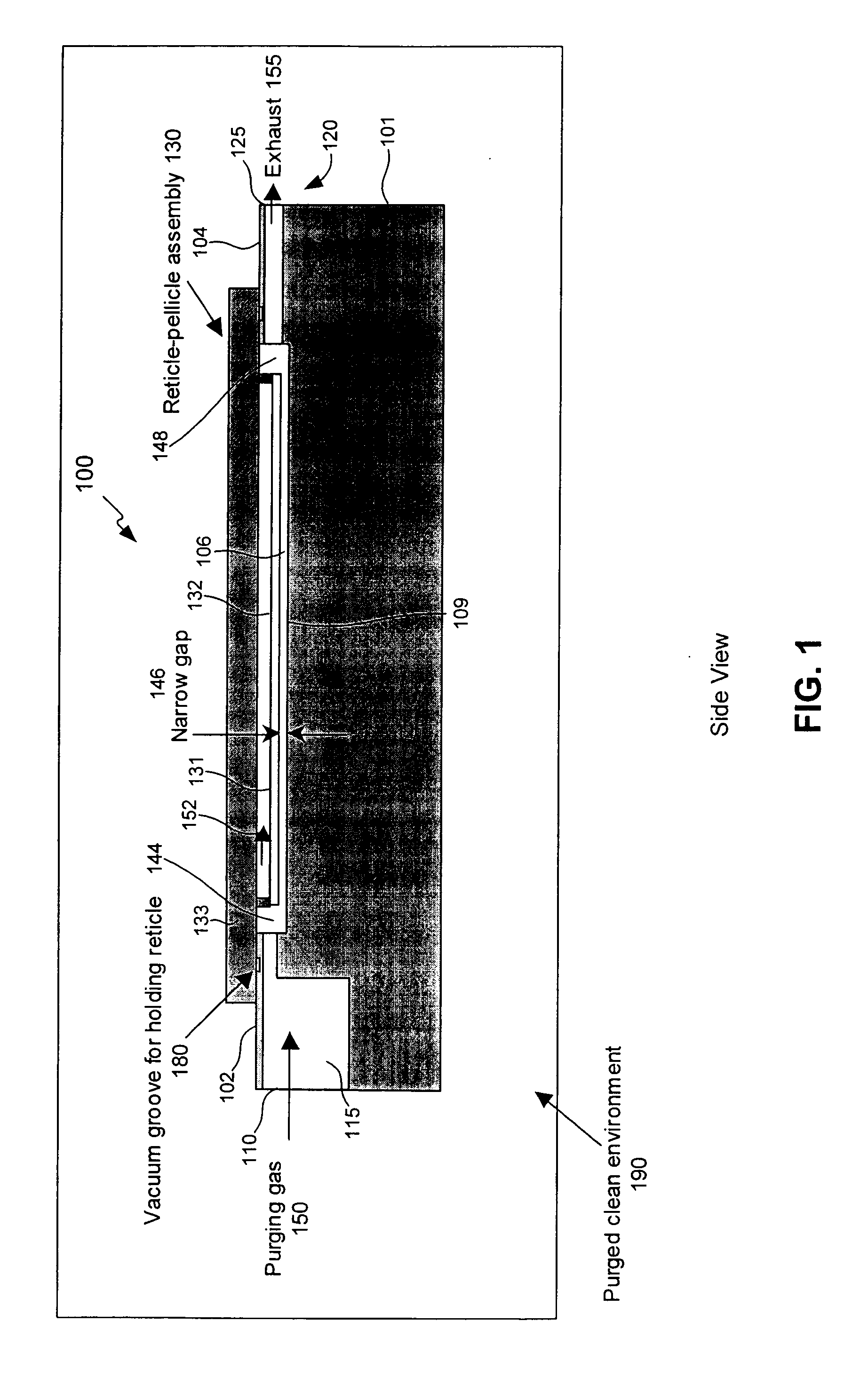
[0036] Purge Device

[0037]FIG. 1 is a cross-sectional diagram of a purge device 100 in a side view according to an embodiment of the present invention. Purge device 100 is disposed inside a controlled environment 190 that is filled with a desired purge gas. ...


PUM

PropertyMeasurementUnit
exposure wavelengthaaaaaaaaaa
volumeaaaaaaaaaa
pressureaaaaaaaaaa

Abstract

The present invention provides methods and systems for fast purging of pellicle volumes. A purge device has a base which is enclosed in a controlled environment filled with purge gas. The base a cavity formed on a surface therein. The cavity receives a reticle-pellicle assembly including a pellicle surface and an enclosed pellicle volume. A first region within the cavity can be formed to hold purging gas at a high pressure. A gap region is formed below the pellicle within the cavity. A displacement force on the pellicle due to a pressure difference between purging gas in the enclosed volume and purging gas in the gap region is kept within a tolerance range of the pellicle. According to further embodiments, a purge device is provided that includes a flow barrier (e.g., non-contacting and / or contacting barriers). A pressure balancing plate and / or flow resistant plates are provided in a purge device.

Description

BACKGROUND OF THE INVENTION [0001] 1. Field of the Invention [0002] The present invention relates to purging, and in particular to purging pellicle volumes in lithography. [0003] 2. Related Art [0004] In lithography, a reticle is often protected by a pellicle. A pellicle is mounted on a stand-off (also called a pellicle frame) from the reticle. The space enclosed by a reticle, a pellicle frame, and a pellicle, is called the pellicle volume. In some lithographic applications, such as 157 nm wavelength exposure applications, a pellicle volume needs to be purged and filled with a certain quality of a certain gas before the reticle can be exposed. For example, in 157 nanometer (nm) applications, nitrogen (pure or nearly pure) is often used to fill a pellicle volume before a reticle can be exposed for printing patterns on wafers. [0005] To accomplish purging of a pellicle volume, gas can passively diffuse into the pellicle volume space. Such passive gas diffusion, however, takes a long t...

Claims


Application Information

Patent Timeline
Patent Type & Authority Applications(United States)
IPC IPC(8): B65D85/86G03F1/14F04B39/00G03F7/20H01L21/027
CPCG03F1/64G03F7/70983G03F7/70933
Inventor LUO, CI FLORENCEVOGEL, HERMANHARROLD, GEORGE HILARYKATE, NICOLAAS TEN
Owner ASML HLDG NV
Learn More