
Motor controller

a technology of motor controller and control apparatus, which is applied in the direction of dynamo-electric converter control, dynamo-electric gear control, pulse technique, etc., can solve the problems of failure or breakage of semiconductor devices for electric power, and the inability to obtain desired accuracy of an estimated life, so as to reduce the amplitude of changes in temperature of semiconductor devices.

Inactive Publication Date: 2005-03-31
MITSUBISHI ELECTRIC CORP
View PDF9 Cites 61 Cited by
  • Summary
  • Abstract
  • Description
  • Claims
  • Application Information

AI Technical Summary

Benefits of technology

The invention is an electric motor control apparatus that can adjust the frequency and voltage of an electric motor to control its speed and torque. It includes a current computation part that measures the current flow through the semiconductor device, a temperature change estimation part that calculates the temperature change based on the current, the operating frequency, and the carrier frequency, a power cycle curve data storage part that stores the relationship between temperature change and the lifespan of the semiconductor device, a thermal stress computation part that converts the temperature change into the number of power cycles, and a life estimation part that calculates the expected lifespan of the semiconductor device based on the thermal stress and alerts when the lifespan is shorter than expected. The apparatus also includes an automatic adjustment function to decrease the current limit value and the carrier frequency to decrease the temperature change and satisfy the expected lifespan. Overall, the invention provides accurate life estimation and efficient control of electric motors.

Problems solved by technology

That is, it results in failure or breakage of the semiconductor device for electric power.
In Patent Reference 1, there was a problem that a value of the difference between junction temperatures changes normally but the value of the difference between junction temperatures is set to a fixed value by selecting typical one point in operations and stops of the apparatus and desired accuracy of an estimated life cannot be obtained.

Method used


Image

  • Motor controller
  • Motor controller
  • Motor controller

Examples


first embodiment

[0022] First Embodiment

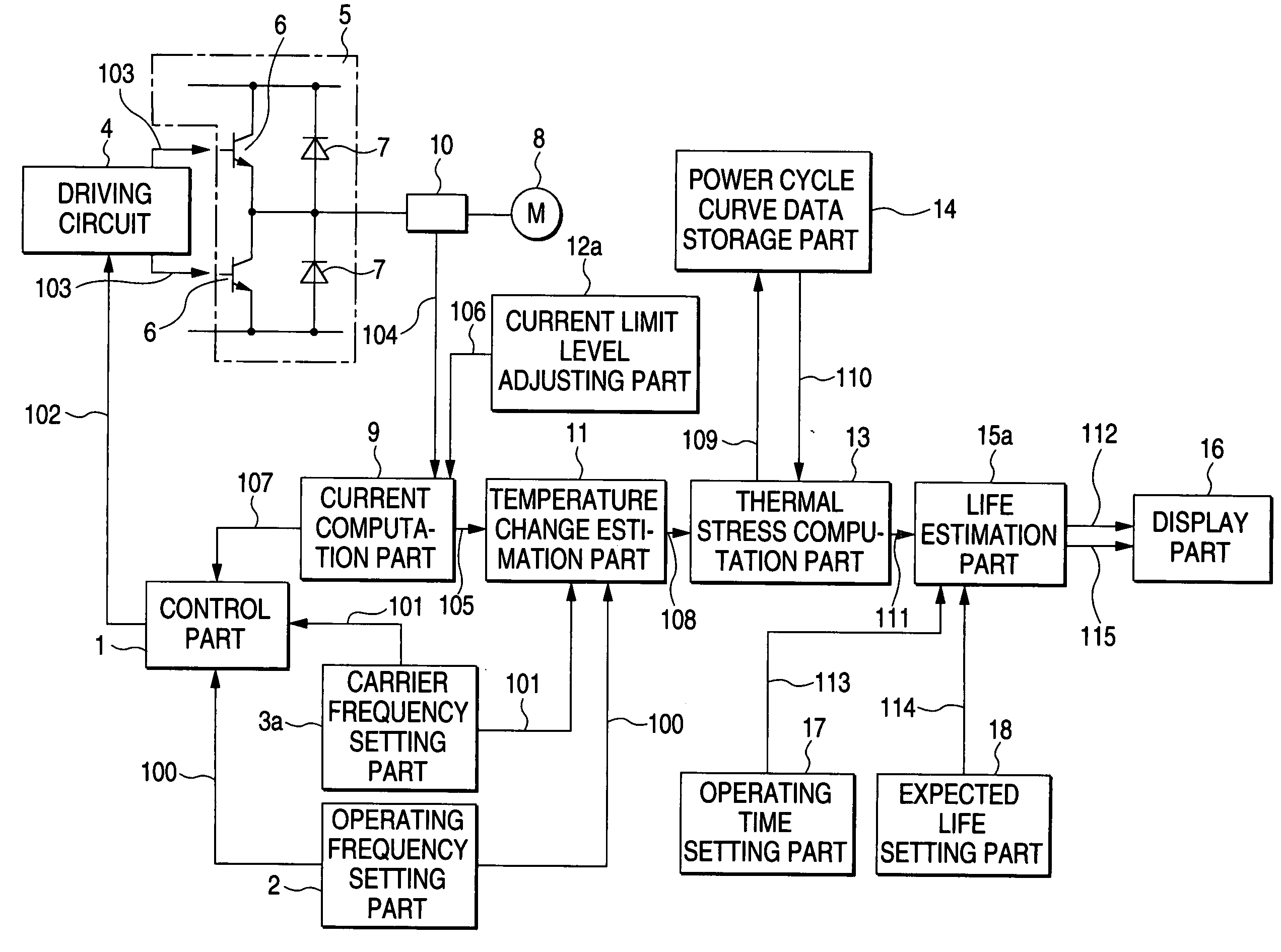
[0023]FIG. 1 is a diagram showing a configuration of an electric motor control apparatus according to a first embodiment of this invention. In the diagram, a control part 1 generates a driving pulse 102 based on an operating frequency signal 100 set by an operating frequency setting part 2 and a carrier frequency signal 101 set by a carrier frequency setting part 3a, and outputs the driving pulse to a driving circuit 4. The driving circuit 4 generates a driving pulse 103 amplified by the driving pulse 102 and performs on-off control of power transistors 6 from which a switching circuit 5 is constructed and thereby, DC electric power is converted into AC electric power of a variable frequency and a variable voltage and variable control of an electric motor 8 acting as a load is performed. Also, numerals 7 are diodes connected in parallel with the power transistors 6.

[0024] Also, a current computation part 9 computes an output current from a current detection s...

second embodiment

[0041] Second Embodiment

[0042]FIG. 6 is a diagram showing a configuration of an electric motor control apparatus according to a second embodiment of this invention. In the diagram, numerals 1, 2, 4 to 11, 13, 14, 16 to 18, 100 to 115 are similar to those of FIG. 1 and the description is omitted.

[0043] A life estimation part 15b outputs a life estimation result signal 112 and a life determination signal 115 to a carrier frequency setting part 3b and a current limit level adjusting part 12b.

[0044] When a summative thermal stress coefficient X included in the inputted life estimation result signal 112 approximates to 1, or when the life determination signal 115 outputted in the case that life time tL falls below an expected life te is inputted, the current limit level adjusting part 12b makes an automatic adjustment so as to decrease a current limit value signal 106 outputted to a current computation part 9.

[0045] When a life of a semiconductor device such as power transistors 6 and...


PUM


Abstract

An electric motor control apparatus of this invention estimates changes in temperature of a semiconductor device to compute temperature change amplitude 108 based on an output current signal 105 computed from a current flowing through the semiconductor device of a switching circuit 5, an operating frequency signal and a carrier frequency signal by a temperature change estimation part 11, and makes conversion into the number of power cycles 110 corresponding to the temperature change amplitude 108 from power cycle curve data stored in a power cycle curve data storage part 14 and computes a thermal stress signal 111 by a thermal stress computation part 13, and does life estimation of the semiconductor device based on the thermal stress signal 111 and produces an output to a display part 16 as a life estimation result signal 112 by a life estimation part 15a.

Description

TECHNICAL FIELD [0001] This invention relates to an electric motor control apparatus for performing variable speed control of an electric motor. BACKGROUND ART [0002] In an electric motor control apparatus such as an inverter apparatus using a semiconductor device for electric power, at the time of an operation of the apparatus, the semiconductor device for electric power generates heat and a junction temperature of a chip increases and at the time of a stop of the apparatus, the heat generation stops and the junction temperature decreases. Also, at the time of starting and stopping an operation of an electric motor and the time of a sudden change in a load, an output current of the apparatus changes largely, so that the junction temperature of the semiconductor device for electric power also changes largely. As a result of this, thermal expansion and thermal shrinkage of a chip portion of the semiconductor device for electric power are repeated due to repeats of the operations and ...

Claims


Application Information

Patent Timeline
Patent Type & Authority Applications(United States)
IPC IPC(8): G01R31/26H02M7/48H02P21/14H02P21/22H02P23/07H02P23/14H02P27/06H02P27/08H03K17/08H03K17/082
CPCH02M7/48H03K2017/0806H03K17/0826H02M2001/327H02M1/327H02P27/06
Inventor KATOU, MASANORI
Owner MITSUBISHI ELECTRIC CORP
Learn More