Pulse duty cycle automatic correction device and method thereof
- Summary
- Abstract
- Description
- Claims
- Application Information
AI Technical Summary
Benefits of technology
Problems solved by technology
Method used
Image

Examples
Embodiment Construction
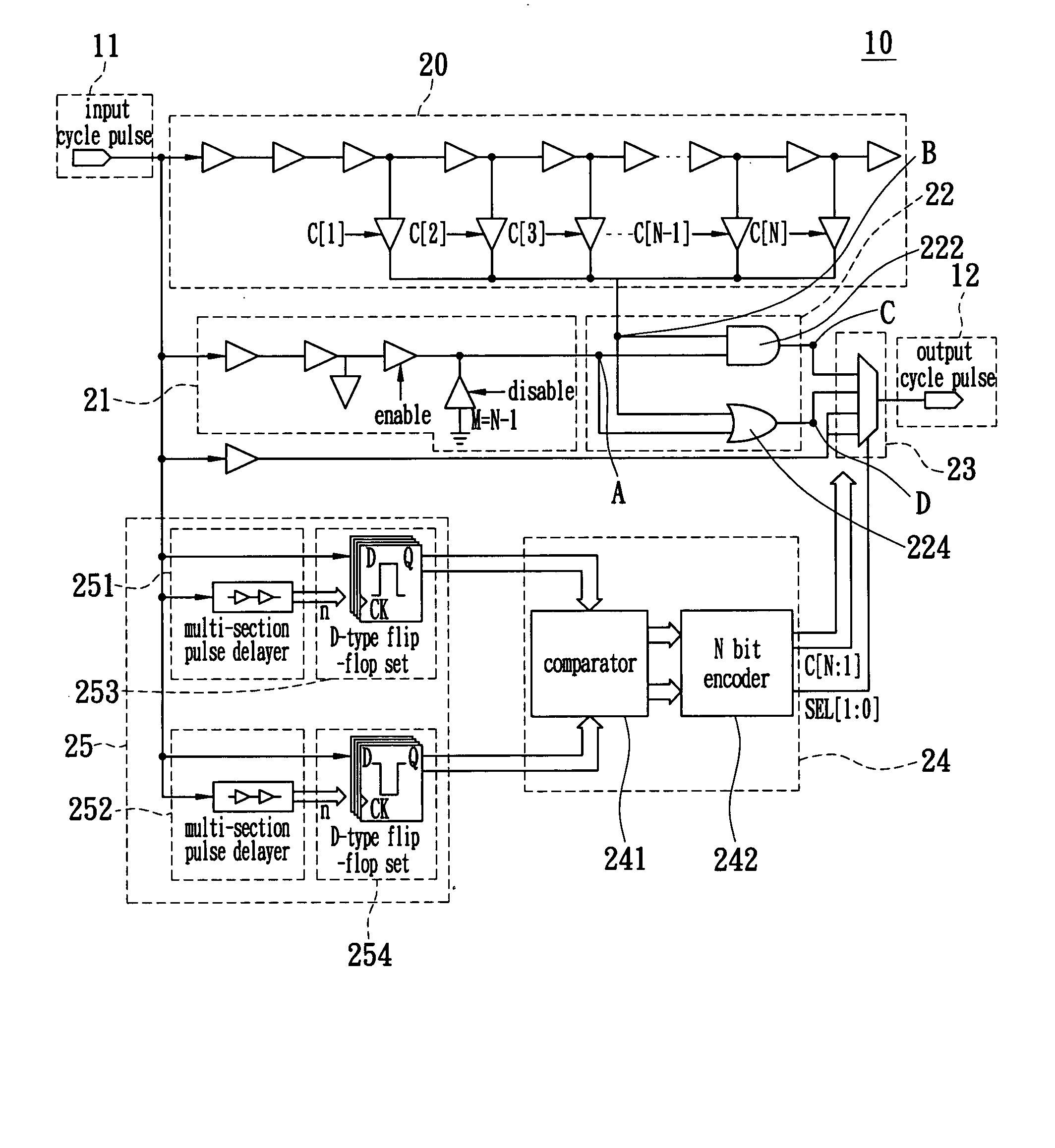
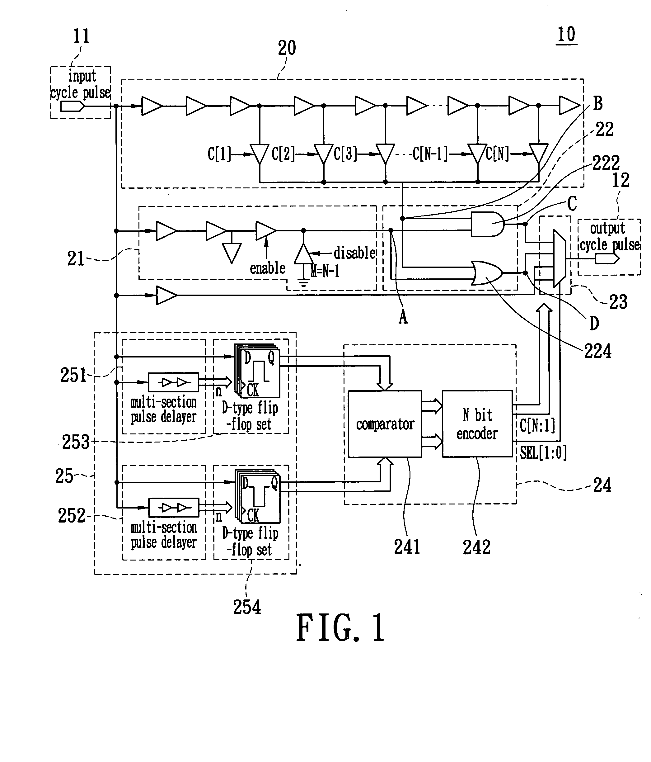
[0016] Reference is made to FIG. 1. FIG. 1 is a block diagram of a pulse duty cycle automatic correction device 10 according to the present invention. The pulse duty cycle automatic correction device 10 will generate a proportional cycle pulse according to the input cycle pulse 11, namely, an output cycle pulse 12. The pulse duty cycle automatic correction device 10 comprises a delay circuit 20, a compensation circuit 21, a logic circuit 22, a multiplexer 23, a comparator encoder 24, and a pulse width detector 25.
[0017] The pulse width detector 25 is composed of multi-section pulse delayers 251, 252 and D-type flip-flop sets 253, 254. The multi-section pulse delayers 251, 252 are separately connected to the D-type flip-flop sets 253, 254, and each of the D-type flip-flop sets 253, 254 comprises a plurality of D-type flip-flops. The pulse width detector 25 is used for receiving the input cycle pulse 11 and separately detecting the high level pulse width (DH) and the low level pulse ...
PUM
 Abstract
Description
Claims
Application Information
 - R&D
- Intellectual Property
- Life Sciences
- Materials
- Tech Scout
- Unparalleled Data Quality
- Higher Quality Content
- 60% Fewer Hallucinations
Browse by: Latest US Patents, China's latest patents, Technical Efficacy Thesaurus, Application Domain, Technology Topic, Popular Technical Reports.
© 2025 PatSnap. All rights reserved.Legal|Privacy policy|Modern Slavery Act Transparency Statement|Sitemap|About US| Contact US: help@patsnap.com