A long-distance laser stress detection method and detector
A stress detection and long-distance technology, which is applied in the direction of measuring the change of optical properties of materials when they are stressed, can solve problems such as difficulty in detection, improve spatial resolution, realize detection, and accurately distinguish the source of signals Effect
- Summary
- Abstract
- Description
- Claims
- Application Information
AI Technical Summary
Problems solved by technology
Method used
Image
Examples
Embodiment 1
[0034] The remote laser stress detection method provided in this embodiment includes the following steps:
[0035] Step S1, emitting two incident laser beams on the same optical path to irradiate the object to be detected.
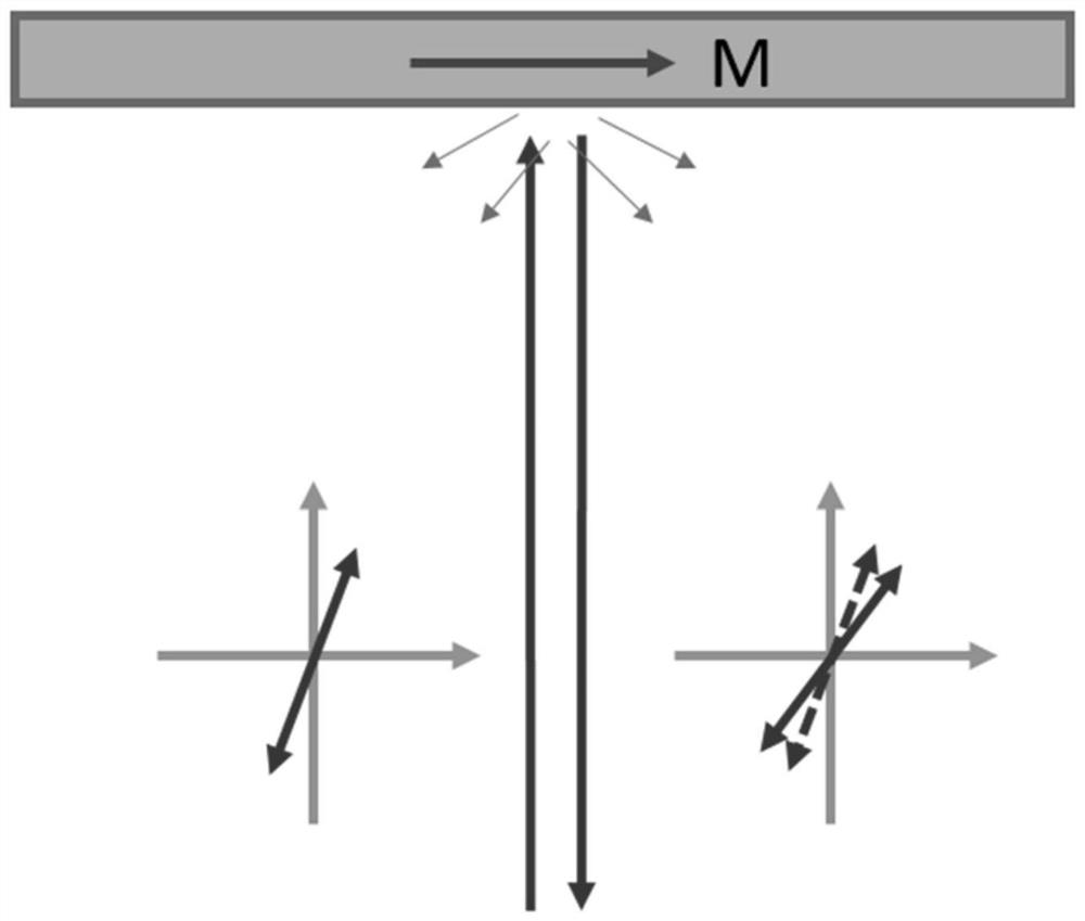
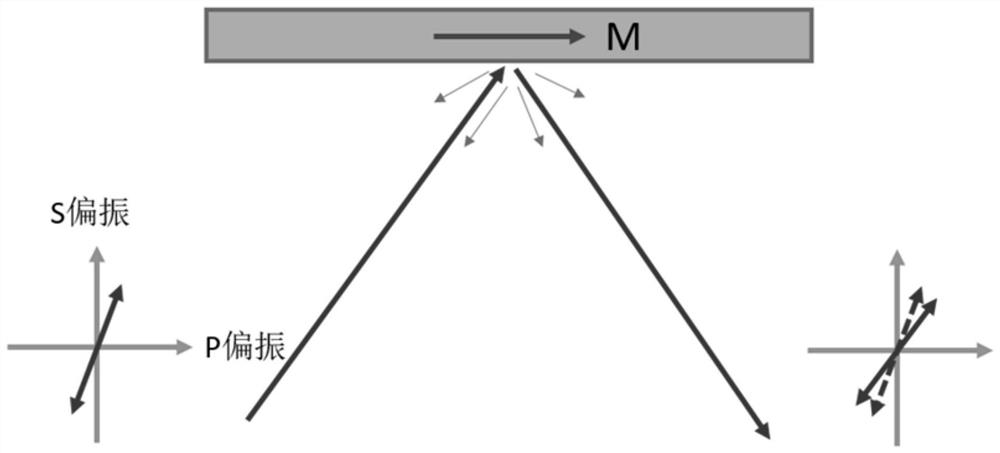
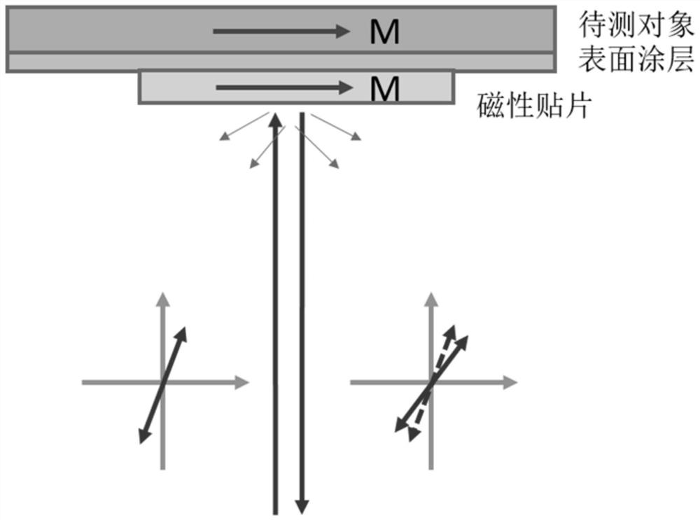
[0036] refer to figure 1 As shown, the polarized incident laser is straightened, and then exits from the hand-held detector to the surface of the object to be measured. In general, linearly polarized light is incident on the surface of the object to be inspected, and when the incident angle is perpendicular to the incident angle, the reflected light returns from the original path. At this time, the polarization direction of the reflected light is rotated, and when the magnetization of the object to be detected is not very large, the polarization angle of the reflected light is linearly related to the magnitude of the magnetization M. In actual situations, it is difficult to ensure the detection Normal incidence of the laser. Generally there is an angle ...
Embodiment 2
[0046] Embodiment 1 provides a long-distance non-contact detection method, which is applied to a detector. This embodiment discloses the principle structure of the detector, such as Figure 4 As shown, it includes a semiconductor laser 101, a wavelength division multiplexer 102, a beam splitter 103, a collimator 104, an analyzer (there are two paths in the figure, marked 105 and 107 respectively) and a photoelectric probe (also two paths , marked 106 and 108 respectively), the semiconductor laser 101 emits laser light to the wavelength division multiplexer 102, and then forms two beams of polarized incident laser light through the beam splitter 103, and after the two beams of incident laser light are straightened by the collimator 104, Irradiate to the object to be detected, and the two reflected lasers returned from the object to be detected pass through the two analyzers, and then irradiate to the two photoelectric probes in one-to-one correspondence. The photoelectric prob...
Embodiment 3
[0048] Embodiment 3 discloses the principle structure of the detector. This embodiment discloses the specific results of a long-distance laser stress detector, including a housing 1, a handle 2 on the back of the housing 1, and a piece on the handle 3. The liquid crystal display screen 3 and the left, right, up movement and confirmation buttons are used for simple operation of the detector, and the buttons are uniformly marked as 4, and the semiconductor laser, wavelength division multiplexer, beam splitter, collimator, and polarizer and photoelectric probes are located within the housing. This hand-held design has a compact structure and is easy to carry, and can realize stress non-contact and fast scanning detection.
PUM
 Abstract
Description
Claims
Application Information
 - R&D
- Intellectual Property
- Life Sciences
- Materials
- Tech Scout
- Unparalleled Data Quality
- Higher Quality Content
- 60% Fewer Hallucinations
Browse by: Latest US Patents, China's latest patents, Technical Efficacy Thesaurus, Application Domain, Technology Topic, Popular Technical Reports.
© 2025 PatSnap. All rights reserved.Legal|Privacy policy|Modern Slavery Act Transparency Statement|Sitemap|About US| Contact US: help@patsnap.com


