
Radial shaft seal and method for making same

a technology of radial shaft and sealing rod, which is applied in the direction of engine seals, mechanical devices, engine components, etc., can solve the problems of tension loss, increased frictional moment of torque of the overall system, etc., and achieves low frictional forces and good sealing properties.

Inactive Publication Date: 2005-03-31
CARL FREUDENBERG KG
View PDF18 Cites 13 Cited by
  • Summary
  • Abstract
  • Description
  • Claims
  • Application Information

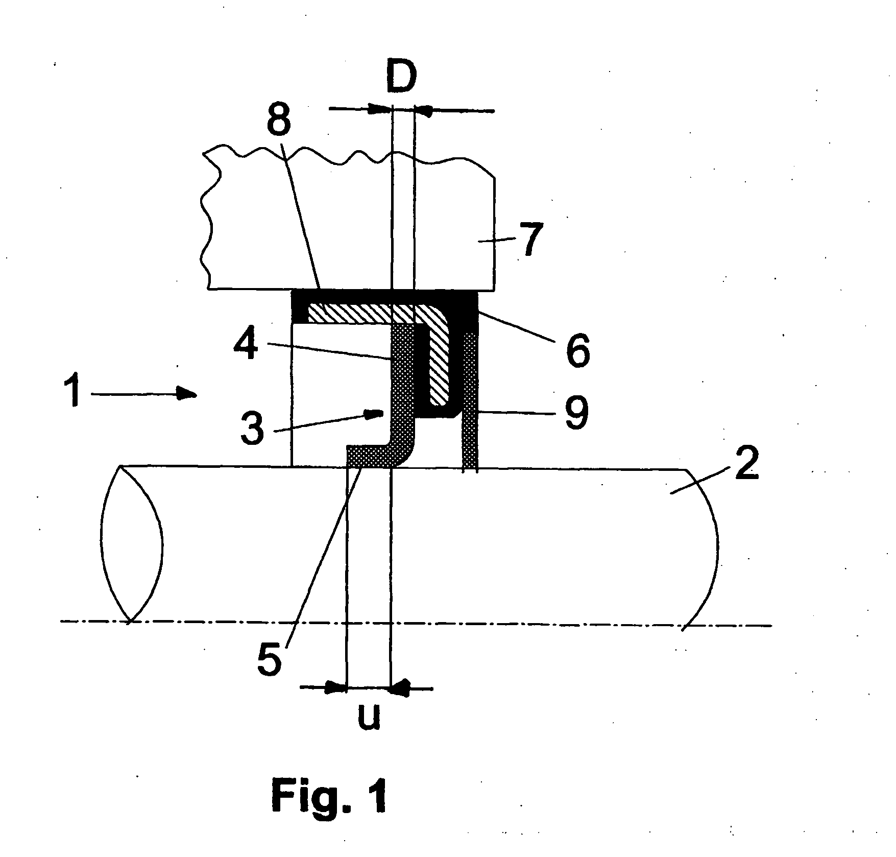
AI Technical Summary

Benefits of technology

[0005] The object of the invention is to provide a radial shaft seal with good sealing properties, particularly during long-term use, that generates low frictional forces and that can also be economically fabricated.
[0008] A preferred non-woven fabric is a mechanically bonded one. The mechanical bonding of the non-woven fabric can be accomplished, for example, by water-jet bonding or needling. This provides good mechanical support as well as an open structure and porosity. Moreover, the non-woven fabric can be made of fibers or fiber blends of polyamide, polybenzimidazole, polyester, glass fibers, aramide fibers, polyacrylic fibers or basalt fibers. The fibers, preferably, are 2-100 mm and particularly 3-20 mm long and have a weight per unit area of 20 to 500 g / m2. The relative shortness of the fibers ensures high porosity which is advantageous for the subsequent impregnation.
[0010] To this end, in an additional processing step, the PTFE non-woven fabric sealing web is subjected in a continuous rolling or lamination process, with the aid of rotating, heated steel rollers, to a heat and pressure treatment which on one side results in marked densification of the PTFE non-woven fabric web (highly oil-tight) and at the same time, because of the spreading action of the rollers, leads to marked surface smoothing. This results in improved frictional behavior, lower dirt exposure and no inclusion into the sealing lip of dust and dirt particles from the outside or of carbonized oil particles from the inside.
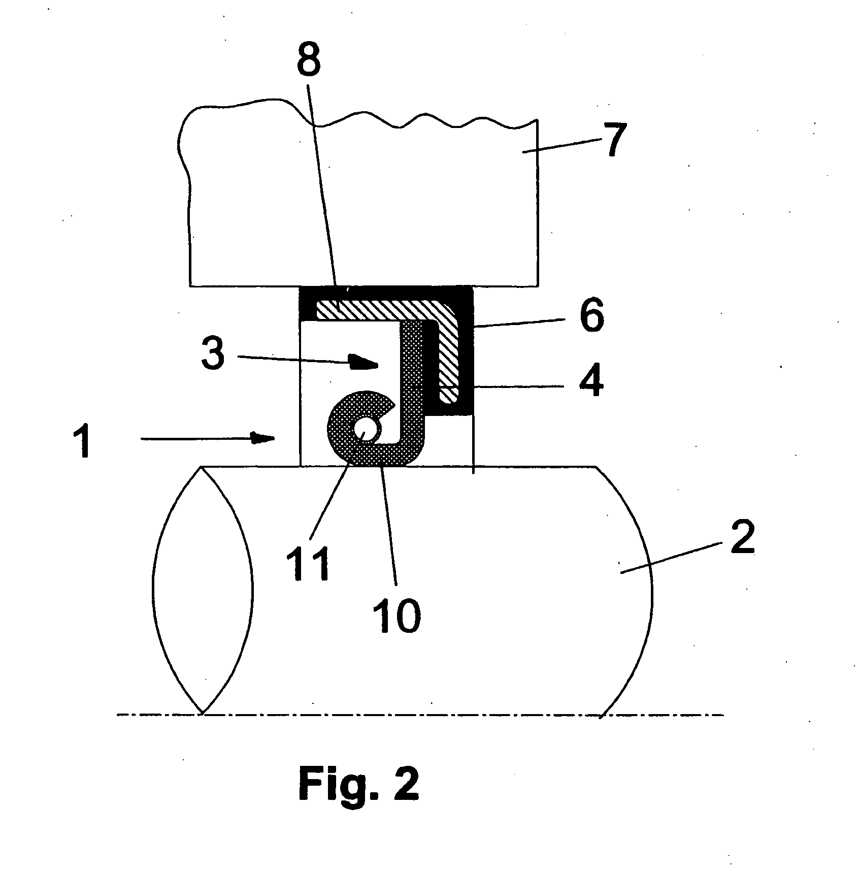
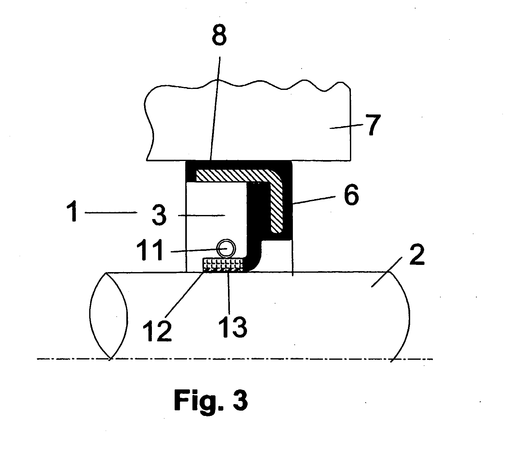
[0011] The sealing elements themselves are fabricated by punching them out of the laminated non-woven fabric webs. To complete the radial shaft seal, the elements are connected to fastening elements which in themselves are known and are inserted into appropriate housing openings. For this purpose, the sealing element is provided with an annular disk having a fastening collar and a sealing hub forming the sealing surface. The sealing hub that rests on the shaft is configured so that it provides a certain overlap. As a result of this overlap, the sealing hub resting on the shaft is readily bent when it is pulled onto the shaft. In case of a larger overlap, it may be advantageous to press the sealing hub against the shaft by a coiled spring. For protection of the coiled spring against particle inclusions, the spring can also be completely enveloped by a highly flexible non-woven fabric web.
[0012] The sealing elements can also be configured as dust protectors. As a result of the low frictional coefficient of the new sealing element, the dust protector can, with its inner edge, be in contact with the shaft without thus causing an undesirably high frictional moment of torque. The method of producing the radial shaft seal with a sealing element made of a non-woven fabric impregnated with an active material, particularly PTFE, and disposed between a stationary machine part and a rotating shaft is characterized in that mechanically bonded non-woven fabric webs made of fibers having a length of 3-100 mm and particularly 3 to 20 mm are impregnated with an aqueous PTFE dispersion, then dried, and finally a predetermined number of the webs is laminated either individually or to each other by use of heat and pressure. It is advantageous if, after impregnation, the non-woven fabric webs are passed between squeeze rollers.

Problems solved by technology

This, however, results in a marked increase in the frictional moment of torque of the overall system.
Such seals, however, have the drawback that PTFE has a tendency to creep, particularly at high temperatures, which can cause tension losses and thus leaks.

Method used


Image

  • Radial shaft seal and method for making same
  • Radial shaft seal and method for making same
  • Radial shaft seal and method for making same

Examples


example

[0034] To prepare a radial shaft seal, 1.0-mm-thick non-woven fabric webs were made from 8-15 mm-long fibers. The non-woven fabric webs were impregnated with an aqueous PTFE dispersion and then passed through squeeze rollers. They were then dried in a continuous oven at a temperature of 260° C. and laminated in a compressing apparatus. Annular sealing elements were punched out of the resulting laminate and inserted into a shaft seal. The radial shaft seal was pushed over a shaft, the diameter of which was slightly larger than the inner diameter of the sealing element opening. This resulted in a slight bending of the sealing element edge, the overlap amounting to about 1.5 mm. The performance of the seal in terms of friction and tightness was surprisingly good.


PUM


Abstract

A radial shaft seal with a sealing element made of a non-woven fabric impregnated with an active material, particularly PTFE. The shaft seal is disposed between a stationary machine part and a rotating shaft. In the axial direction, the sealing element consists of at least one layer of non-woven fabric impregnated with a PTFE dispersion and laminated under pressure and heat.

Description

CROSS-REFERENCE TO RELATED APPLICATIONS [0001] This application is a National Stage of International Application No. PCT / EP02 / 07035, filed Jun. 26, 2002. This application claims the benefit of German Patent Application 101 48 715.0, filed Oct. 2, 2001. The disclosures of the above applications are incorporated herein by reference.FIELD OF THE INVENTION [0002] Numerous seals are known for sealing shafts that rotate within a stationary housing. Frequently used are seals known as lip seals involving a lip-shaped sealing element made of an elastomer that surrounds the shaft in a sealing manner. With aggressive media, sealing lips made of a PTFE material are also in use. To complement the seals, dirt-collecting aprons consisting of a simple felt disk are often used on the air side. If the dirt-collecting aprons are extended as far as the shaft, they additionally have a sealing function. This, however, results in a marked increase in the frictional moment of torque of the overall system. ...

Claims


Application Information

Patent Timeline
Patent Type & Authority Applications(United States)
IPC IPC(8): F16J15/32F16J15/3228F16J15/3244F16J15/3288
CPCF16J15/3228F16J15/3288F16J15/3244
Inventor KLENK, THOMASLIEDTKE, ULRICHSCHULTZ, FRANKBOCK, EBERHARDWETZEL, STEPHAN
Owner CARL FREUDENBERG KG
Learn More