Edge exposing apparatus
- Summary
- Abstract
- Description
- Claims
- Application Information
AI Technical Summary
Benefits of technology
Problems solved by technology
Method used
Image
Examples
first embodiment
[0074] First Embodiment
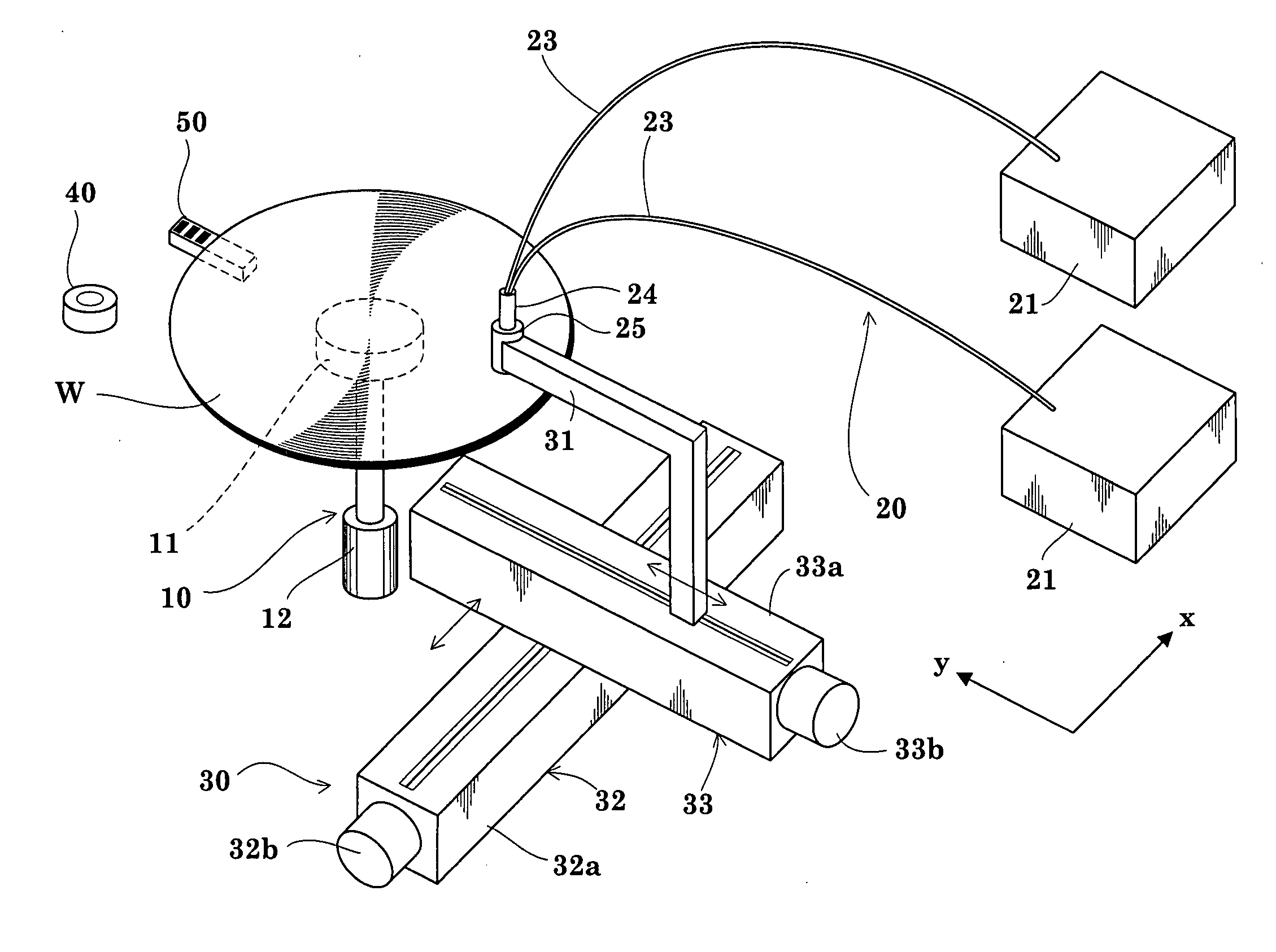
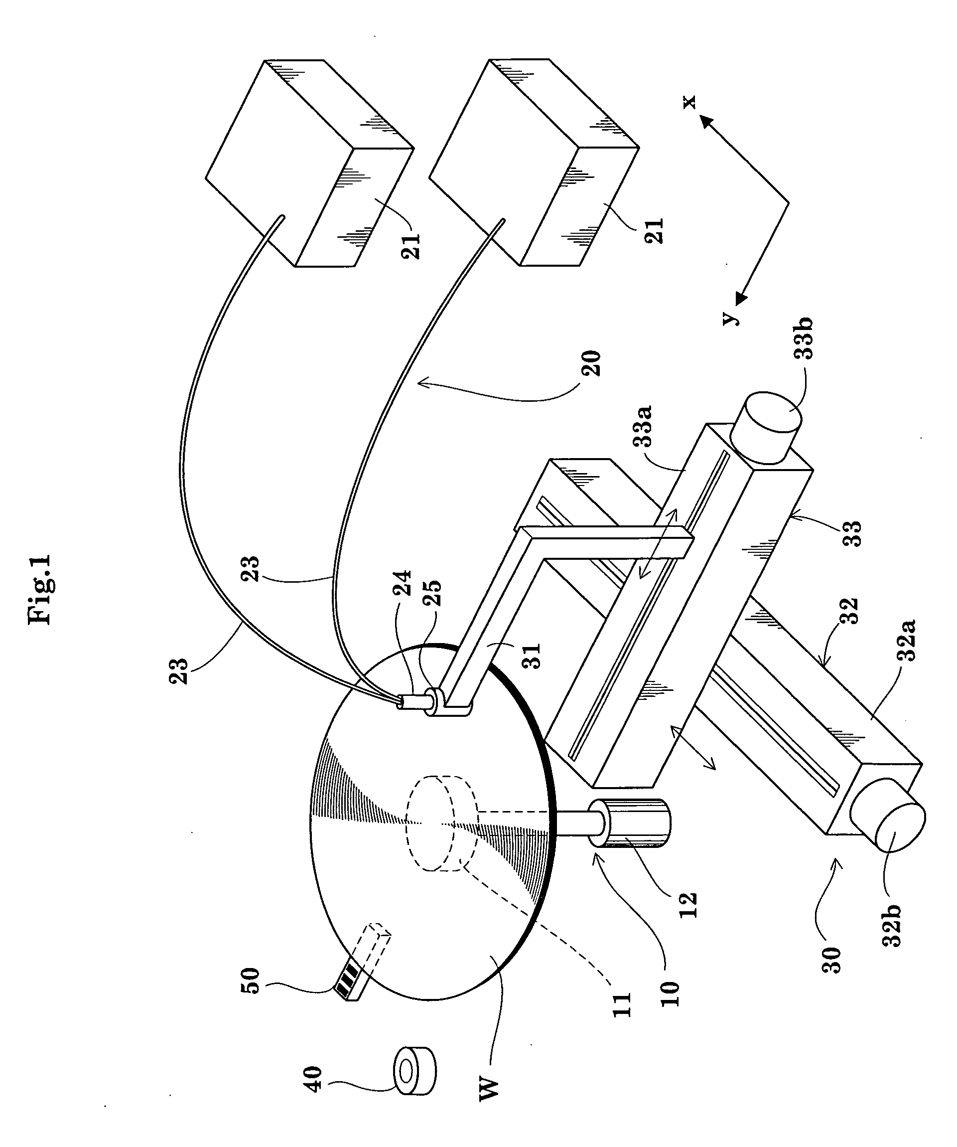
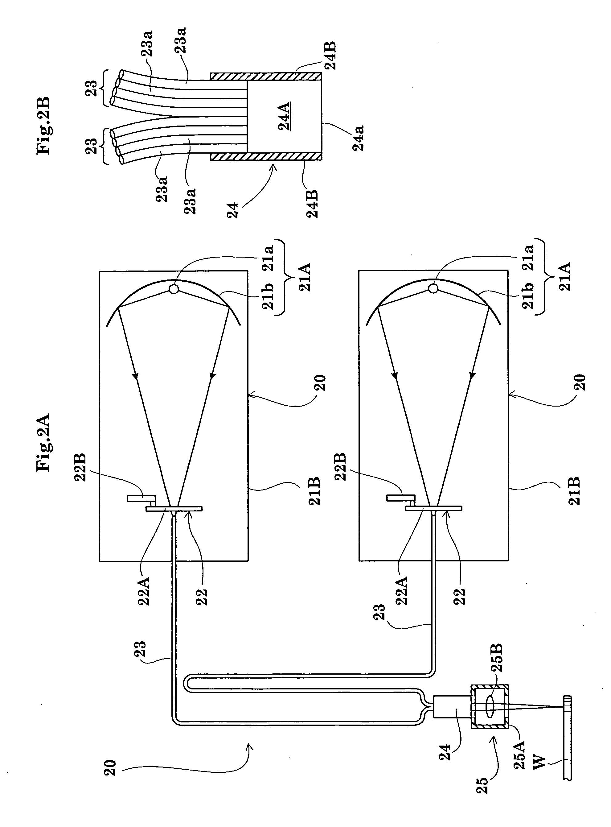
[0075]FIG. 1 is a perspective view showing an outline of an edge exposing apparatus in a first to a third embodiments of the invention. FIG. 2A is a view showing an outline of a treating mechanism. FIG. 2B is an enlarged view of a quartz rod and adjacent components shown in FIG. 2A. FIG. 3 is a block diagram of a control system.
[0076] As shown in FIG. 1, the apparatus in the first embodiment includes a substrate spinning mechanism 10 having a spin chuck 11, a treating mechanism 20 having light source units 21, light guides 23 and an irradiation head 25, and a moving mechanism 30 for moving the irradiation head 25 in a horizontal plane (xy plane).
[0077] The substrate spinning mechanism 10 includes the spin chuck 11 and a spin motor 12. The spin chuck 11 supports a wafer W in horizontal posture by suction. The spin chuck 11 is connected to the spin motor 12 to be rotatable about a vertical axis to spin the wafer W as suction-supported about the vertical axis, ...
second embodiment
[0116] Second Embodiment
[0117] The second embodiment of this invention will be described next with reference to the drawings.
[0118]FIGS. 6 and 7 are flow charts of an edge exposing operation in the second embodiment. FIGS. 8 and 9 are timing charts of the edge exposing operation in the second embodiment. The apparatus in the second embodiment has the same construction as in the first embodiment, and will not be described again.
[0119] In the second embodiment, an edge exposing process from start of edge exposure to switch-off is carried out with the two light source units 21. As in the first embodiment, one of the two light source units 21 will be referred to as “light source unit 211”, and the other as “light source unit 212”. In the second embodiment, and in the third embodiment described hereinafter, the lights emitted from the light source units 211 and 212 are mixed by the light mixing optical element 24A. The mixed light is used to irradiate the edge regions of wafer W to per...
third embodiment
[0157] Third Embodiment
[0158] The third embodiment of this invention will be described next with reference to the drawings.
[0159]FIGS. 10 and 11 are flow charts of an edge exposing operation in the third embodiment. FIG. 12 is a timing chart of the edge exposing operation in the third embodiment. The apparatus in the third embodiment has the same construction as in the first and second embodiments, and will not be described again.
[0160] In the third embodiment, as in the second embodiment, an edge exposing process from start of edge exposure to switch-off is carried out with the two light source units 21. The third embodiment is useful where one of the two light source units is identified as distinguished from the other.
[0161] (Step U1) has the Lighting Time of the Light Source Units Reached a Preset Value?
[0162] While an edge exposing operation with the two light source units 211 and 212 is in progress, the lighting time measuring circuit 63 measures a lighting time (irradiation...
PUM
 Abstract
Description
Claims
Application Information
 - R&D
- Intellectual Property
- Life Sciences
- Materials
- Tech Scout
- Unparalleled Data Quality
- Higher Quality Content
- 60% Fewer Hallucinations
Browse by: Latest US Patents, China's latest patents, Technical Efficacy Thesaurus, Application Domain, Technology Topic, Popular Technical Reports.
© 2025 PatSnap. All rights reserved.Legal|Privacy policy|Modern Slavery Act Transparency Statement|Sitemap|About US| Contact US: help@patsnap.com


