Endpoint compensation in electroprocessing

a technology of electroprocessing and endpoint compensation, which is applied in the direction of manufacturing tools, lapping machines, electric circuits machining, etc., can solve the problems of time-consuming methods, impede the accurate determination of the polishing endpoint, and the progress of the polishing operation is not easily viewabl

Inactive Publication Date: 2005-03-24
APPLIED MATERIALS INC
View PDF99 Cites 30 Cited by
  • Summary
  • Abstract
  • Description
  • Claims
  • Application Information

AI Technical Summary

Benefits of technology

In general, embodiments are relating to process control of electro-processing. Some aspects of the invention are generally directed to determining removal of material from a wafer during polishing, to determining an endpoint of a poli

Problems solved by technology

However, the progress of the polishing operation is not easily viewable because of the contact between the wafer and the pad.
In addition, variations in the polishing conditions impede an accurate determination of the polishing endpoint.
However, this method is time consuming, and does not account for sudden changes in the removal rate that may occur between measurement intervals.
However, this method does not provide a way of determining the polishing endpoint unless an underlying layer is exposed during polishing.
Additionally, this approach is somewhat erratic in predicting the polishing endpoint unless all of the underlying lines are simultaneously exposed.
Furthermore, t

Method used


Image

  • Endpoint compensation in electroprocessing
  • Endpoint compensation in electroprocessing
  • Endpoint compensation in electroprocessing

Examples


example

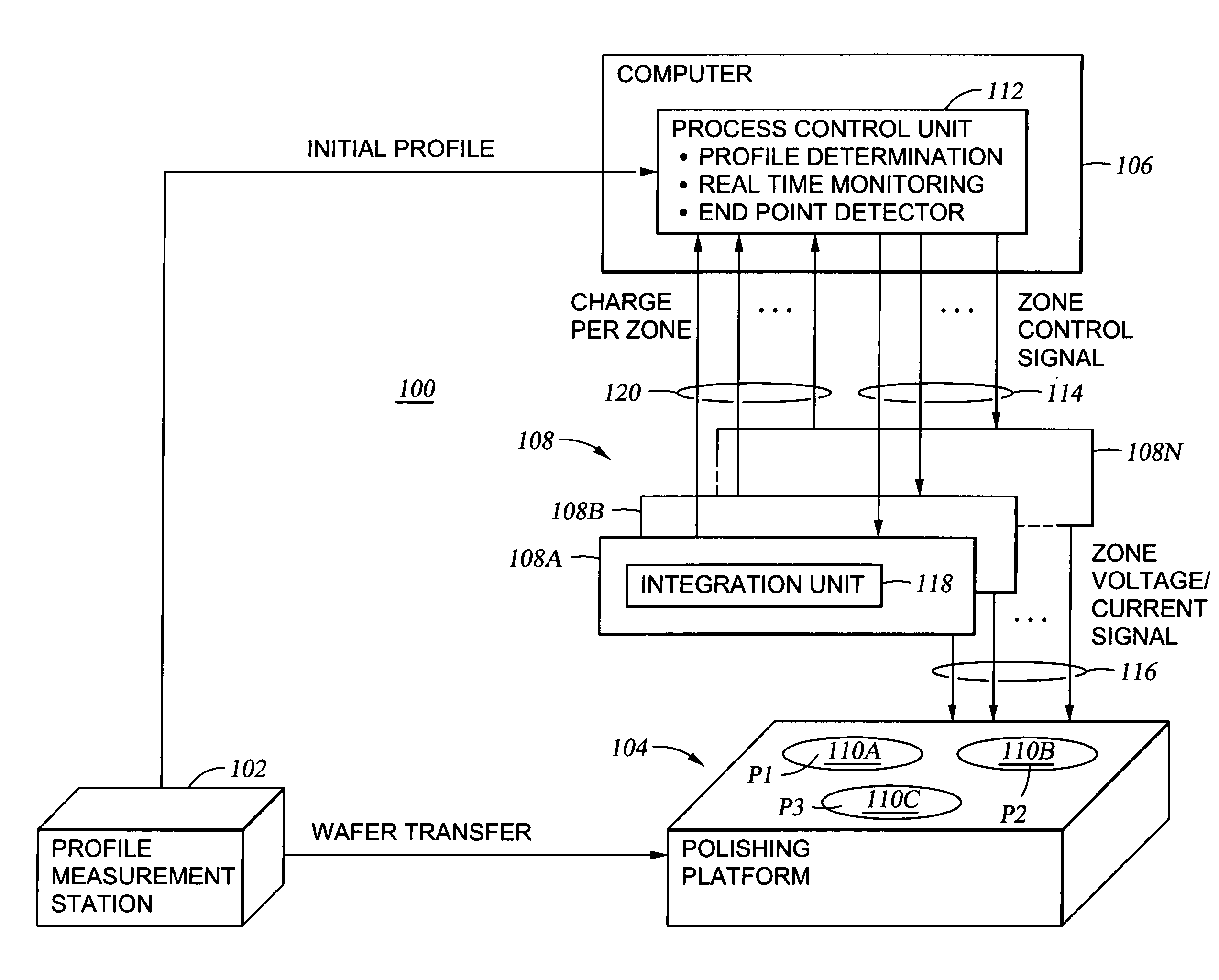
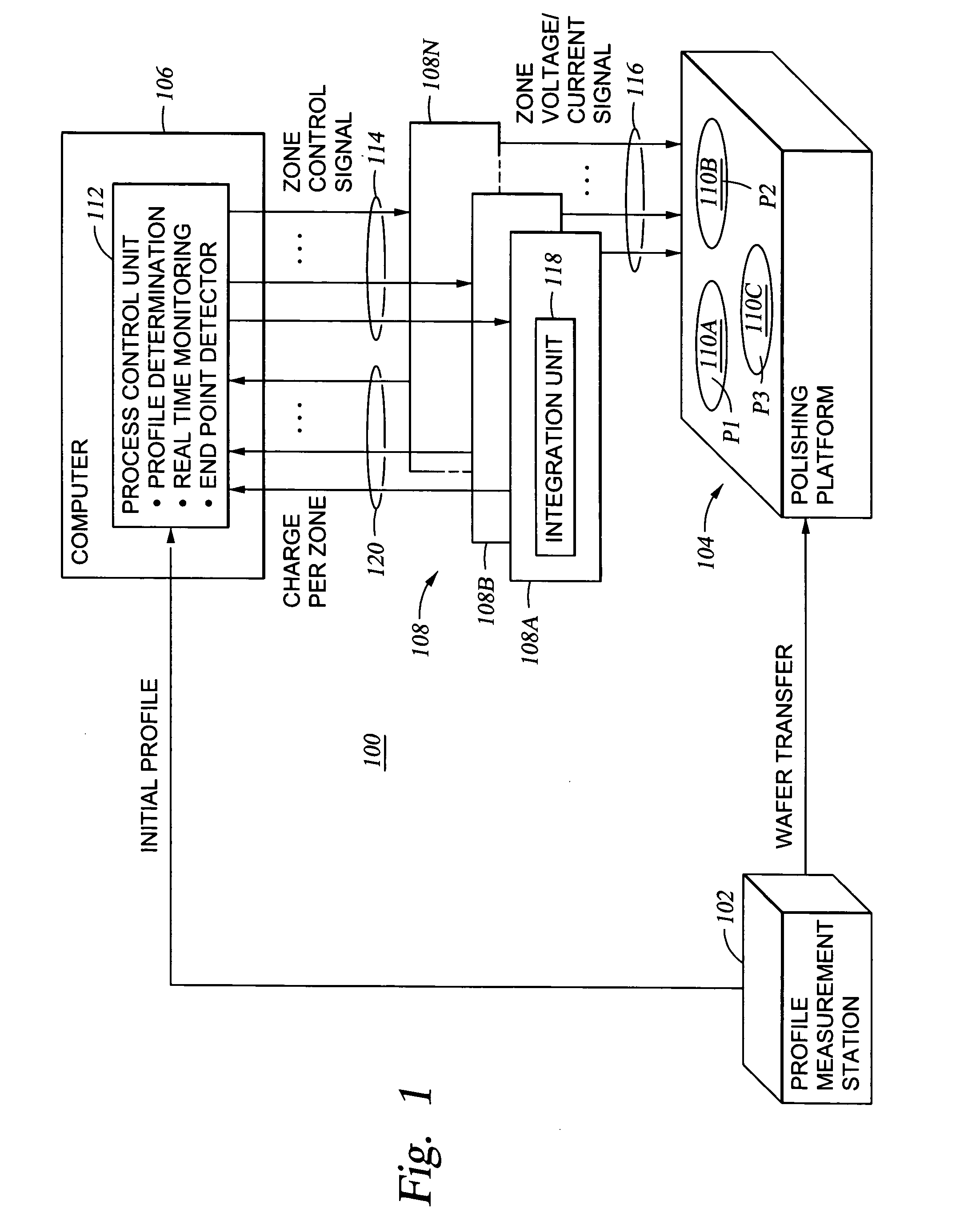
A counter-electrode assembly, such as the counter-electrode assembly 209 was divided into five zones: an inner zone, an inner-central zone, a central zone, an outer-central zone and an outer zone (Z1, Z2, Z3, Z4 and Z5) respectively. The zones were arranged in a concentric circular manner similar to the zones depicted for the electrode assembly 209 shown in FIG. 4. Each of the zones was capable of receiving a separate bias with respect to a material layer of a wafer to be polished. One hundred twenty one points, representing a broad sampling of various locations on the material layer were selected. A pre-determined set of instructions (i.e., a polishing program) that encoded a sequence of relative motion between the counter-electrode (as well as the polishing article) and the material layer of a wafer to be processed was provided to a computer (e.g., the computer 106). An algorithm based on the polishing program was used to determine the sequence of relative positions between the m...


PUM

PropertyMeasurementUnit
Thicknessaaaaaaaaaa
Electric chargeaaaaaaaaaa
Currentaaaaaaaaaa

Abstract

Method for process control of electro-processes is provided. In one embodiment, the method includes processing a conductive layer formed on a wafer using a target endpoint, detecting breakthrough of the conductive layer to expose portions of an underlying layer, and adjusting the target endpoint in response to the detected breakthrough. In another embodiment, the target endpoint is adjusted relative to an amount of underlying layer exposed through the conductive layer.

Description

BACKGROUND OF THE INVENTION 1. Field of the Invention The present invention generally relates to polishing, planarization, plating and combinations thereof. More particularly, the invention relates to the monitoring and control of electro-processing, polishing and plating. 2. Description of the Related Art Sub-quarter micron multi-level metallization is one of the key technologies for the next generation of ultra large-scale integration (ULSI). The multilevel interconnects that lie at the heart of this technology require planarization of interconnect features formed in high aspect ratio apertures, including contacts, vias, trenches and other features. Reliable formation of these interconnect features is very important to the success of ULSI and to the continued effort to increase circuit density and quality on individual wafers and die. In the fabrication of integrated circuits and other electronic devices, multiple layers of conducting, semiconducting, and dielectric materials...

Claims


Application Information

Patent Timeline
IPC IPC(8): B23H5/06B23H5/08B24B37/04B24B49/04B24B49/16H04N1/00
CPCB23H5/06B23H5/08B24B37/013B24B37/042B24B37/046H04N1/00B24B49/10B24B49/16G01N1/32H01L21/32125H01L21/32134B24B49/04
Inventor WANG, YANMANENS, ANTOINE P.NEO, SIEW S.DUBOUST, ALAINCHEN, LIANG-YUH
Owner APPLIED MATERIALS INC
Why Eureka
Try Eureka