
Combustion method with integrated CO2 separation by means of carbonation

a technology of combustion method and carbonation, which is applied in the direction of combustible gas purification/modification, separation process, other chemical processes, etc., can solve the problems of large-scale and very costly installations, large amount of energy, and reduce the yield of generating useful electricity

Inactive Publication Date: 2005-03-24
CONSEJO SUPERIOR DE INVESTIGACIONES CIENTIFICAS (CSIC) +1
View PDF8 Cites 46 Cited by
  • Summary
  • Abstract
  • Description
  • Claims
  • Application Information

AI Technical Summary

Benefits of technology

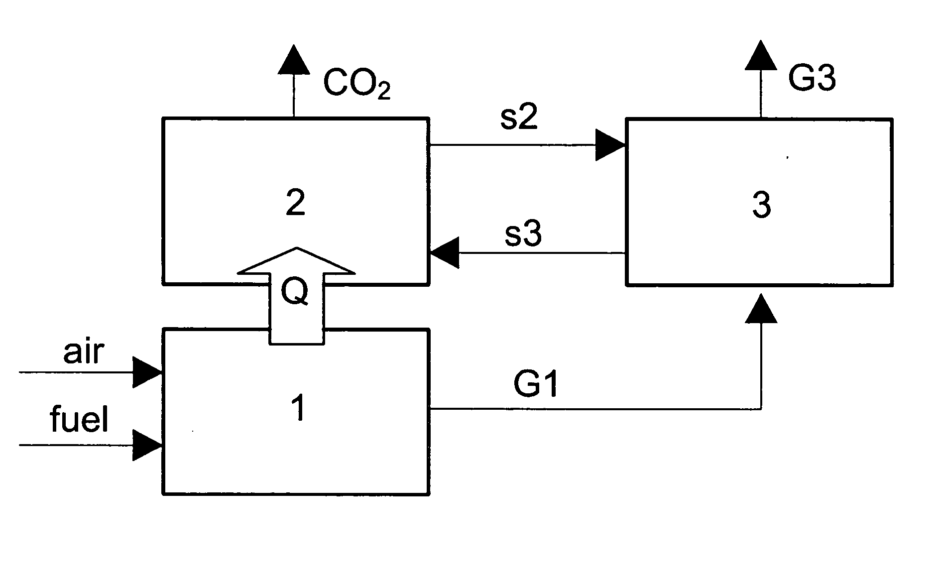
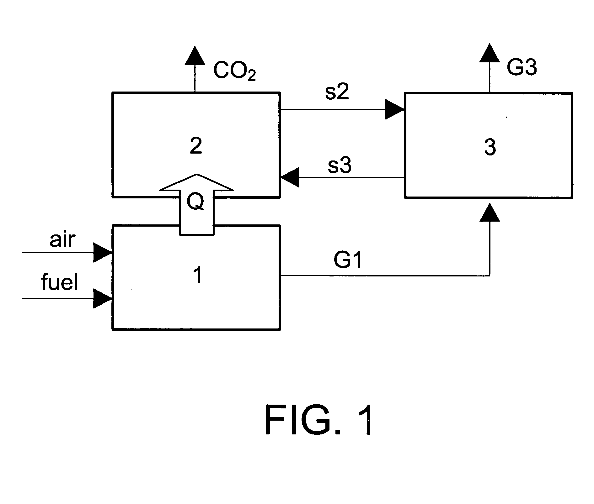
The calciner (2) operates at temperatures lower than 900° C. in atmospheres of pure CO2 or of CO2 / H2O. To reduce the calcination temperature and increase the temperature gradient between (1) and (2) the partial pressure of CO2 in the calciner can be reduced by applying a certain vacuum to (2) and / or injecting steam into (2). The heat exchange between (1) and (2) may be direct through metal walls or indirect by means of using an inert solid (sand, alumina or others) that continuously circulate through (1) and (2) and that is easily separable from the active solids in CO2 capture.

Problems solved by technology

There are a variety of commercial methods for CO2 separation in the oil industry, natural gas industry and chemistry in general, mainly based on low temperature absorption processes, but use thereof for separating CO2 from combustion gases coming from a thermal power station has big limitations (Herzog et al., 1997): the huge amounts of gas to be treated require large-size and very costly installations, require a large amount of energy to regenerate the sorbent which reduces the yields in generating useful electricity and / or heat and the pollutants in the fuel (SO2, NOx) tend to damage the absorbent which creates high operating costs.
All of them are non-commercial methods which are still under development.

Method used


Image

  • Combustion method with integrated CO2 separation by means of carbonation
  • Combustion method with integrated CO2 separation by means of carbonation

Examples


Embodiment Construction

It describes a new combustion method with integrated CO2 separation by means of carbonation based on the use of part of the heat generated in the combustion chamber by the calciner in order to maintain the endothermic reaction of calcination and to regenerate the sorbent, without the need to use an air separating plant; in combination with a carbonator to treat the hot gases and which in turn generate energy during carbonation.

The object of the invention comprises a combustion chamber (1) wherein any type of fuel is burnt with air, preferably at temperatures higher than 1,000° C. generating heat and a stream of combustion gases at a high temperature with a CO2 content between 3 and 17% by volume depending on the fuel and the excess air used in the combustion. The combustion chamber may be of any type, a fluidized bed, a conventional powdered carbon combustion boiler, or natural gas burner or burner of other liquid fuels. Combustion can be done at atmospheric pressure or at a high...


PUM

PropertyMeasurementUnit
temperaturesaaaaaaaaaa
densityaaaaaaaaaa

Abstract

The invention relates to a method for separating CO2 from combustion gases, which can be used at areas with large emissions (thermal power stations using any carbonaceous fuel). The separated CO2 stream can be used and / or contained in geological formations. The inventive method aims to reduce the high costs involved in CO2 separation which prevent large-scale use of the CO2 confinement options included in the UN's IPCC reports. Said method consists of bringing the combustion gases into contact with a calcareous sorbent (limestone, calcined dolomite) at 650-750° C., thereby producing the CO2 capture reaction by means of the rapid carbonation of the sorbent. The sorbent is regenerated in another reactor (calciner) which operates in CO2 or CO2 / H2O atmospheres.

Description

TECHNICAL FIELD Energy sector. Large scale process for generating electricity and / or heat with integrated CO2 separation from the combustion gases. PRIOR ART The UN's International Panel for Climate Change (IPCC, 2001) considers the capturing of CO2 generated from large stationary sources and its subsequent containment in a variety of geological formations as a very interesting middle and long-term option. Use of these technologies require previous obtainment of a highly concentrated stream of CO2 (Herzog et al., 1997). The CO2 content of the combustion gases in different types of thermal power stations varies between 3 and 17% by volume, which makes a previous separation stage necessary. There are a variety of commercial methods for CO2 separation in the oil industry, natural gas industry and chemistry in general, mainly based on low temperature absorption processes, but use thereof for separating CO2 from combustion gases coming from a thermal power station has big limitations ...

Claims


Application Information

Patent Timeline
Patent Type & Authority Applications(United States)
IPC IPC(8): B01D53/34B01D53/62B01J20/04B01J20/34
CPCB01D53/343B01D53/62Y02C10/08B01D2257/504Y02C10/04B01D2251/404Y02A50/20Y02C20/40
Inventor ABANADES GARCIA, JUAN CARLOSOAKEY, JOHN
Owner CONSEJO SUPERIOR DE INVESTIGACIONES CIENTIFICAS (CSIC)
Learn More