
Mixed reactant molecular screen fuel cell

a molecular screen and reactant technology, applied in the field of electrochemical fuel cells and batteries, can solve the problems of insufficient to meet the ever-increasing demand for energy, the current high cost of fuel cells is prohibitive to widespread use, and the production of electricity by combustion remains relatively cheap. , to achieve the effect of reducing the problem of stack sealing and removing the complex manifold

Inactive Publication Date: 2005-03-17
JEROME ALLAN
View PDF1 Cites 49 Cited by
  • Summary
  • Abstract
  • Description
  • Claims
  • Application Information

AI Technical Summary

Benefits of technology

[0012] It is an object of the present invention to provide a fuel cell or battery that eliminates the complex manifold and reduces problems associated with stack sealing in a fuel cell.
[0013] It is a further object of the present invention to provide a fuel cell or battery that is relatively compact in size having a relatively high power density.
[0014] It is a further object of the present invention to provide a fuel cell capable of operation at ambient temperatures.

Problems solved by technology

Although these technologies have been successfully exploited in certain environments, they have not proven sufficient to meet the world's ever increasing demands for energy.
The current high costs of fuel cells have proven prohibitive to widespread use.
Further, production of electricity by combustion remains relatively cheap.
Hydrogen is relatively expensive to produce, and its storage in significant quantities creates a substantial explosion risk that must be monitored and minimized.
One device used for extracting and collecting hydrogen is known in the art as a “reformer.” Reformers tend to be relatively expensive, bulky and susceptible to various operating and maintenance problems that render them generally unsuitable for small, portable applications.
Moreover, while reformers can extract hydrogen from fuel mixtures such as methanol and air, undesirable CO and CO2 may be produced, and lengthy startup times for fuel cell operation may be necessary in order for the reformer to heat to its desired operating temperature.
There is thus a considerable degree of flexibility associated with the reactant sources, however, the performance in terms of fuel efficiency and cell voltage (due to parasitic fuel-oxidant reactions) is generally lower than in separate reactant designs.
In addition, the fuel / oxidant mixtures can have a tendency to foul the permeable electrolyte.

Method used


Image

  • Mixed reactant molecular screen fuel cell
  • Mixed reactant molecular screen fuel cell
  • Mixed reactant molecular screen fuel cell

Examples


Embodiment Construction

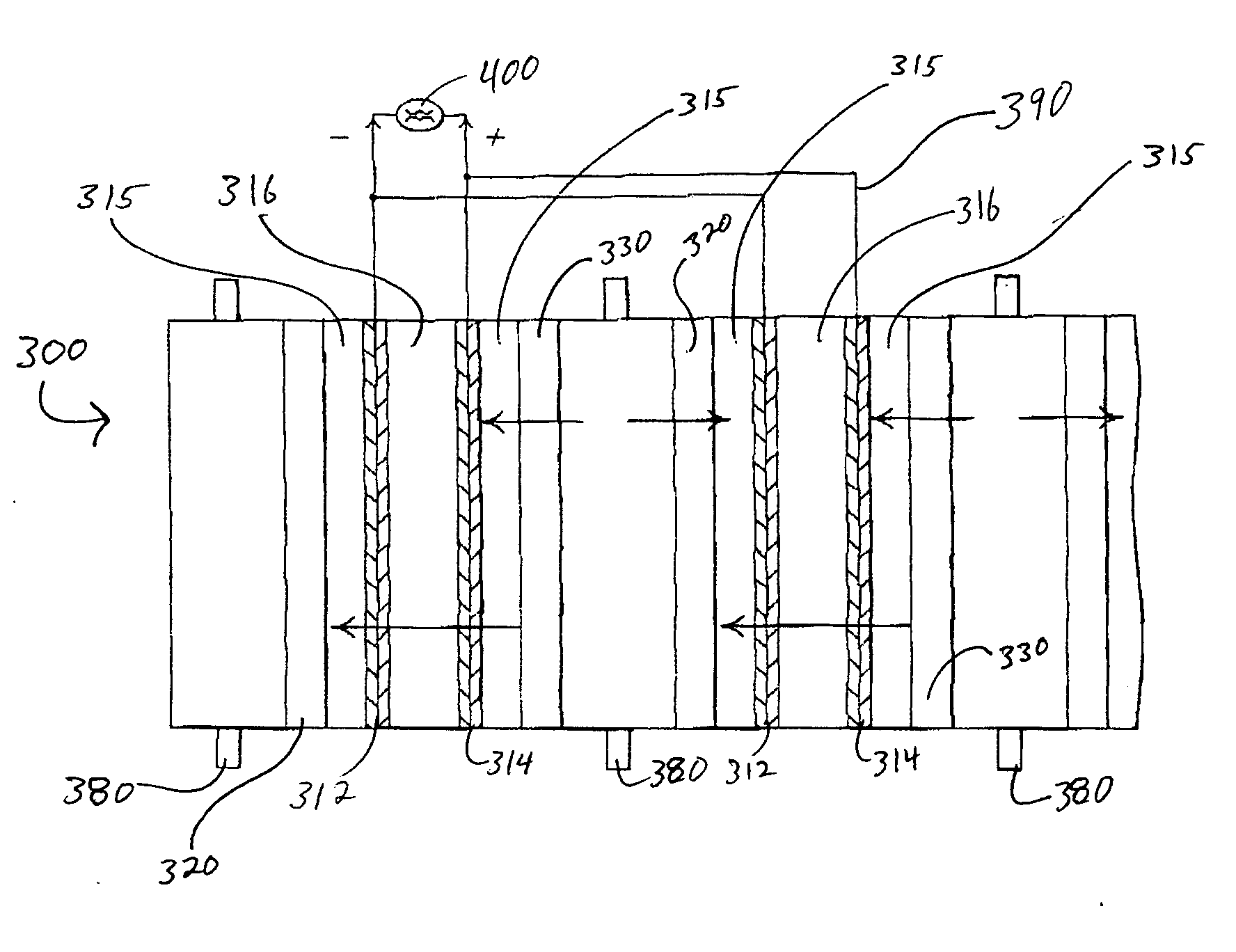
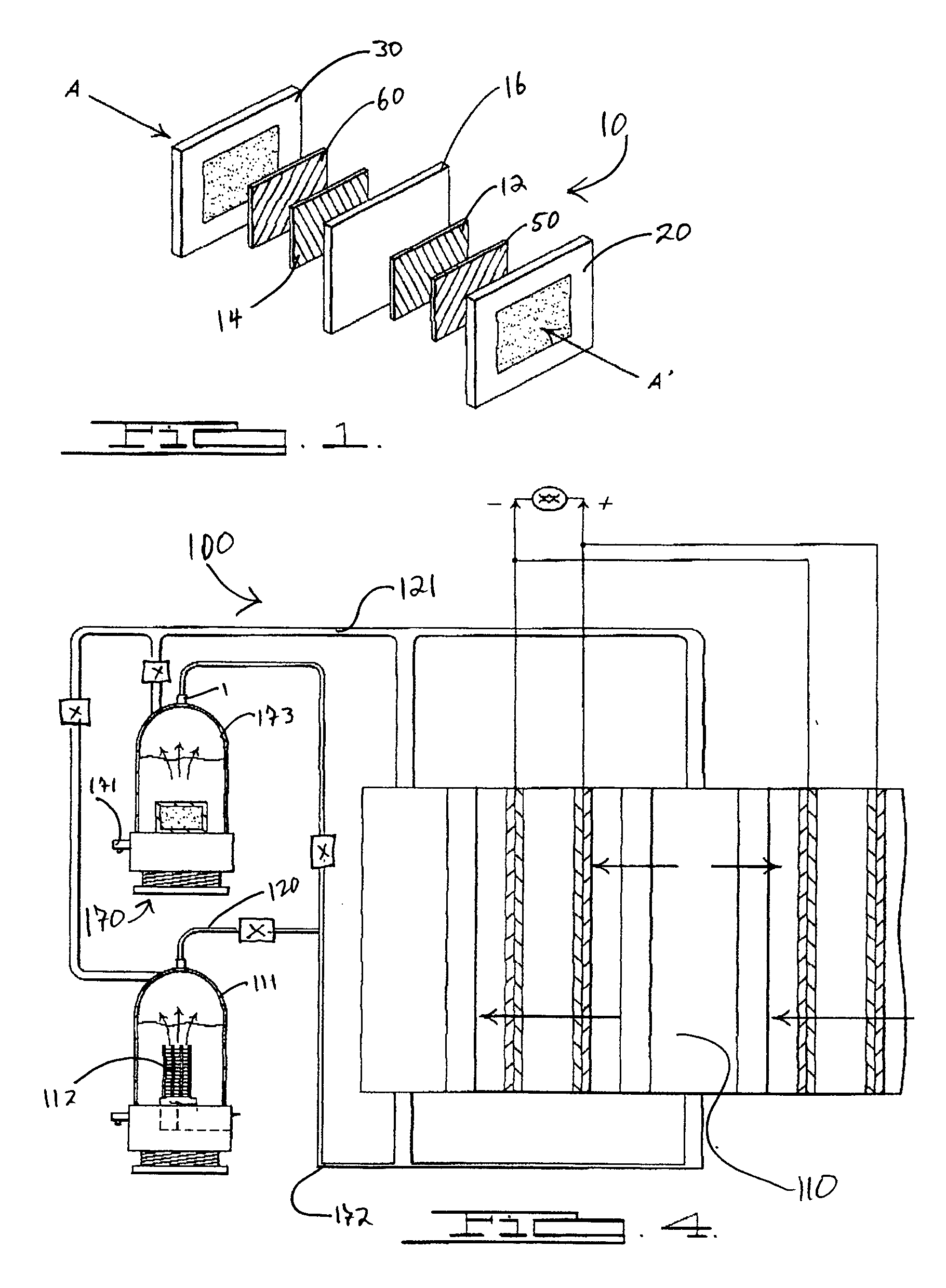
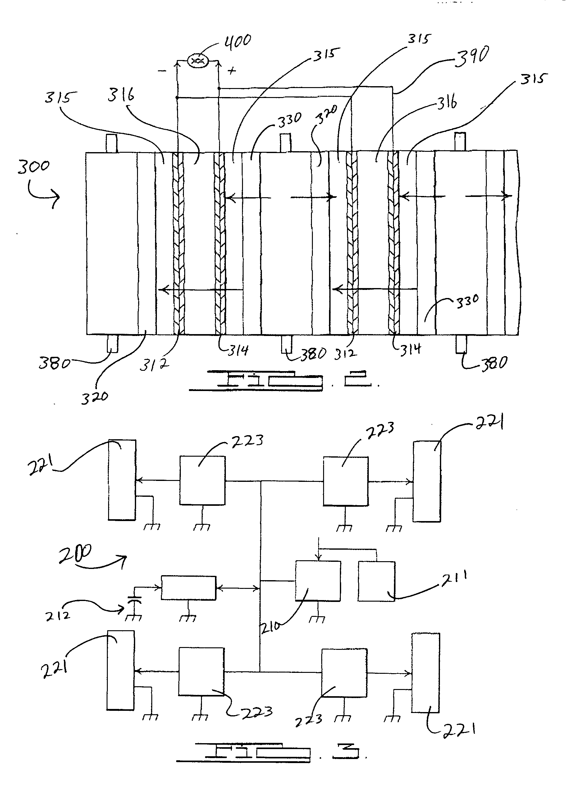
[0024] The present invention broadly comprises a fuel cell or battery having a unique topology wherein separate selectively permeable molecular screens are utilized to separate fuel and oxidizer, respectively, from a mixed reactant supply or stream. This unique topology allows a substantially reduced level of hardware, sealing, valving, etc. in a fuel cell, since the oxidizer and fuel can be generated or stored together, and streams of identical fuel mixture delivered to molecular screens for separation into the fuel and oxidizer components. The separated fuel and oxidizer are subsequently recombined under conditions conducive to their chemical reaction. Oxidation of the fuel results in available electrons that can produce an electrical current for performing work in a well known manner.

[0025] The components of the mixed reactant stream provided to the fuel cell may be essentially any combination of fuel and oxidizer capable of being separated by any known means. Embodiments are co...


PUM

PropertyMeasurementUnit
Electrical conductoraaaaaaaaaa

Abstract

In one aspect, the present invention provides a fuel cell having a first membrane selective to a fuel, a second membrane selective to an oxidant, and a mixed reactant flow provided to the screens. The invention further includes an anode, a cathode and a semi-permeable electrolyte fluidly separating the same.

Description

[0001] This application claims the benefit of the filing date of U.S. Provisional Patent Application Ser. No. 60 / 491,413, filed Jul. 7, 2003, and U.S. Provisional Patent Application Ser. No. 60 / 524,475, filed Nov. 24, 2003.TECHNICAL FIELD [0002] The present invention relates generally to electrochemical fuel cells, batteries and related technologies, and more particularly to an apparatus and process wherein a fuel and oxidant mixture is delivered to separate molecular screens that selectively pass one of the fuel or the oxidant there across for subsequent reaction of the fuel and oxidant and production of an electrical current. BACKGROUND OF THE INVENTION [0003] Depletion of naturally occurring petroleum coupled with increasing concern over environmental degradation resulting from the burning of petroleum and coal is driving a search for alternative energy sources. For many years, wind, water and solar power, nuclear power, and other non-petroleum sources have been exploited to addr...

Claims


Application Information

Patent Timeline
IPC IPC(8): H01M4/86H01M8/02H01M8/04H01M8/06H01M8/16H01M16/00
CPCH01M4/8605Y02T90/32H01M8/0232H01M8/0236H01M8/0239H01M8/0245H01M8/04089H01M8/04291H01M8/0612H01M8/065H01M8/0656H01M8/0687H01M8/16H01M16/003H01M2250/20H01M2300/0082Y02E60/50H01M4/8657Y02T90/40
Inventor JEROME, ALLAN
Owner JEROME ALLAN
Learn More