Dynamic bass boost apparatus and method
a dynamic boost and bass technology, applied in the direction of electrical transducers, transducer details, electrical apparatus, etc., can solve the problems of excessive cost, inability to produce a high-quality sound output, and excessive complexity
- Summary
- Abstract
- Description
- Claims
- Application Information
AI Technical Summary
Benefits of technology
Problems solved by technology
Method used
Image
Examples
first embodiment
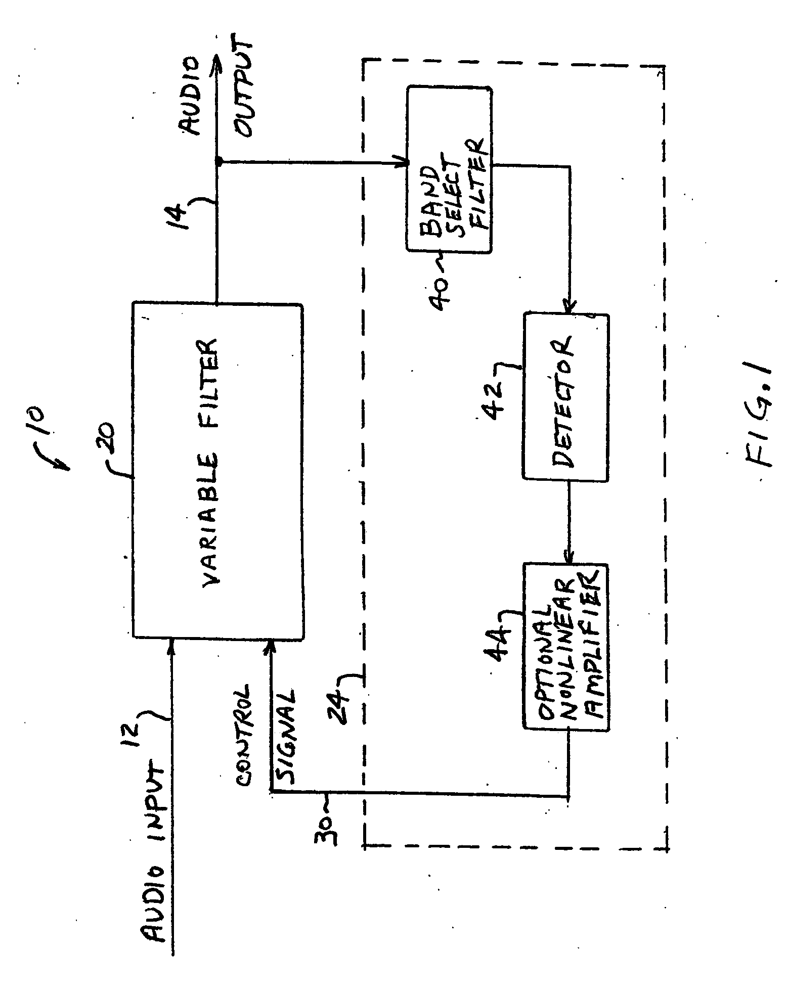
An audio processor, or dynamic bass boost circuit, in accordance with the invention is shown in FIG. 1. A dynamic bass boost circuit 10 receives an audio input signal 12 and provides a filtered audio output signal 14 having controlled bass frequencies so as to at least partially compensate for the Fletcher-Munson effect. Partial compensation for the Fletcher-Munson effect may include enhancement of only selected bass frequencies and / or less than full compensation for the Fletcher-Munson effect at one or more frequencies.
Dynamic bass boost circuit 10 includes a variable filter 20 and a control circuit 24. Control circuit 24 receives audio output signal 14 and provides a control signal 30 to variable filter 20. The control signal 30 controls the frequency characteristic of variable filter 20 as a function of volume level to at least partially compensate for the Fletcher-Munson effect.
Audio input signal 12 may be any suitable audio signal. For example, input signal 12 may be receive...
second embodiment
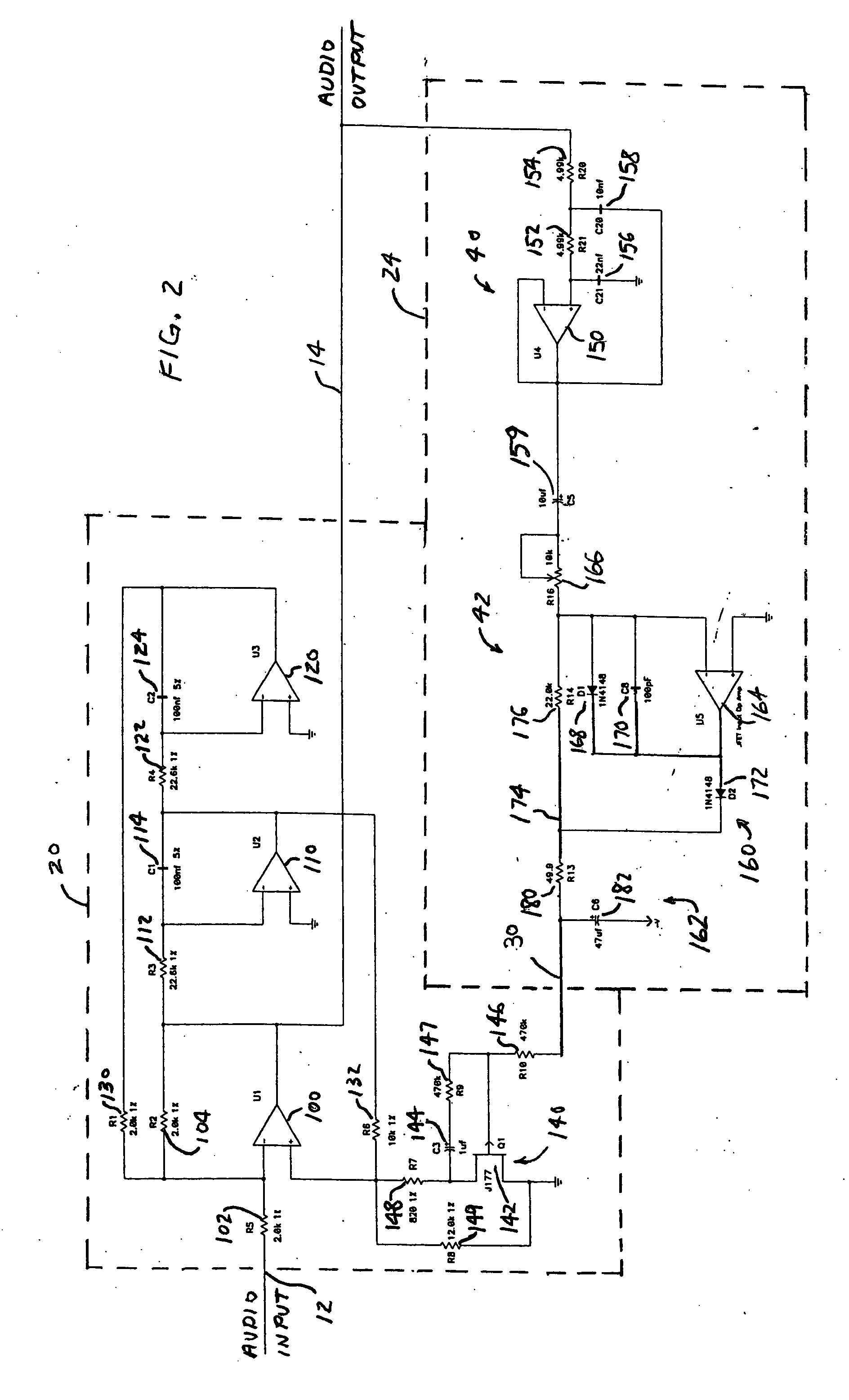
An audio processor in accordance with the invention is shown in FIG. 2. Like elements in FIGS. 1 and 2 have the same reference numerals. The embodiment of FIG. 2 is a specific implementation of the audio processor of FIG. 1, with non-linear amplifier 44 omitted.
In the embodiment of FIG. 2, variable filter 20 is a high-pass, state variable filter. The high-pass, state variable filter 20 includes operational amplifiers 100, 110, and 120 coupled in series. Operational amplifier 100 has an input resistor 102 and a feedback resistor 104, which form a summer. Operational amplifier 110 has an input resistor 112 and a feedback capacitor 114, which form a first integrator. Operational amplifier 120 has an input resistor 122 and a feedback capacitor 124, which form a second integrator. A feedback resistor 130 is connected between the output of amplifier 120 and the inverting input of amplifier 100. A feedback resistor 132 is coupled between the output of amplifier 110 and the non-inverting i...
third embodiment
A schematic block diagram of an audio processor in accordance with the invention as shown in FIG. 4. Like elements in FIGS. 1, 2 and 4 have the same reference numerals. The embodiment of FIG. 4 is another implementation of the audio processor of FIG. 1, with non-linear amplifier 44 omitted. In the embodiment of FIG. 4, voltage-controlled resistor circuit 140 (FIG. 2) is replaced with a resistor 200 connected between the non-inverting input of amplifier 100 and ground, and resistor 132 (FIG. 2) is replaced with a series gain / attenuation element 210 having a signal input connected to the output of amplifier 110 and a signal output connected to the non-inverting input of amplifier 100. The overall operation of the embodiment of FIG. 4 may be the same as the embodiment of FIG. 2, except as to series gain / attenuation element 210 and resistor 200 for controlling the quality factor of variable amplifier 20.
Control signal 30 is supplied from detector 42 to a control input of series gain / at...
PUM
 Abstract
Description
Claims
Application Information
 - R&D
- Intellectual Property
- Life Sciences
- Materials
- Tech Scout
- Unparalleled Data Quality
- Higher Quality Content
- 60% Fewer Hallucinations
Browse by: Latest US Patents, China's latest patents, Technical Efficacy Thesaurus, Application Domain, Technology Topic, Popular Technical Reports.
© 2025 PatSnap. All rights reserved.Legal|Privacy policy|Modern Slavery Act Transparency Statement|Sitemap|About US| Contact US: help@patsnap.com


