Projector
a projector and optical element technology, applied in the field of projectors, can solve the problems of unstable image, high cost of driving circuit, and inability to easily secure the stable operation of the phase modulating optical elemen
- Summary
- Abstract
- Description
- Claims
- Application Information
AI Technical Summary
Benefits of technology
Problems solved by technology
Method used
Image
Examples
first exemplary embodiment
Mode
[0032] The structure of a projector in accordance with a first exemplary embodiment mode of the present invention will next be explained with reference to the drawings.
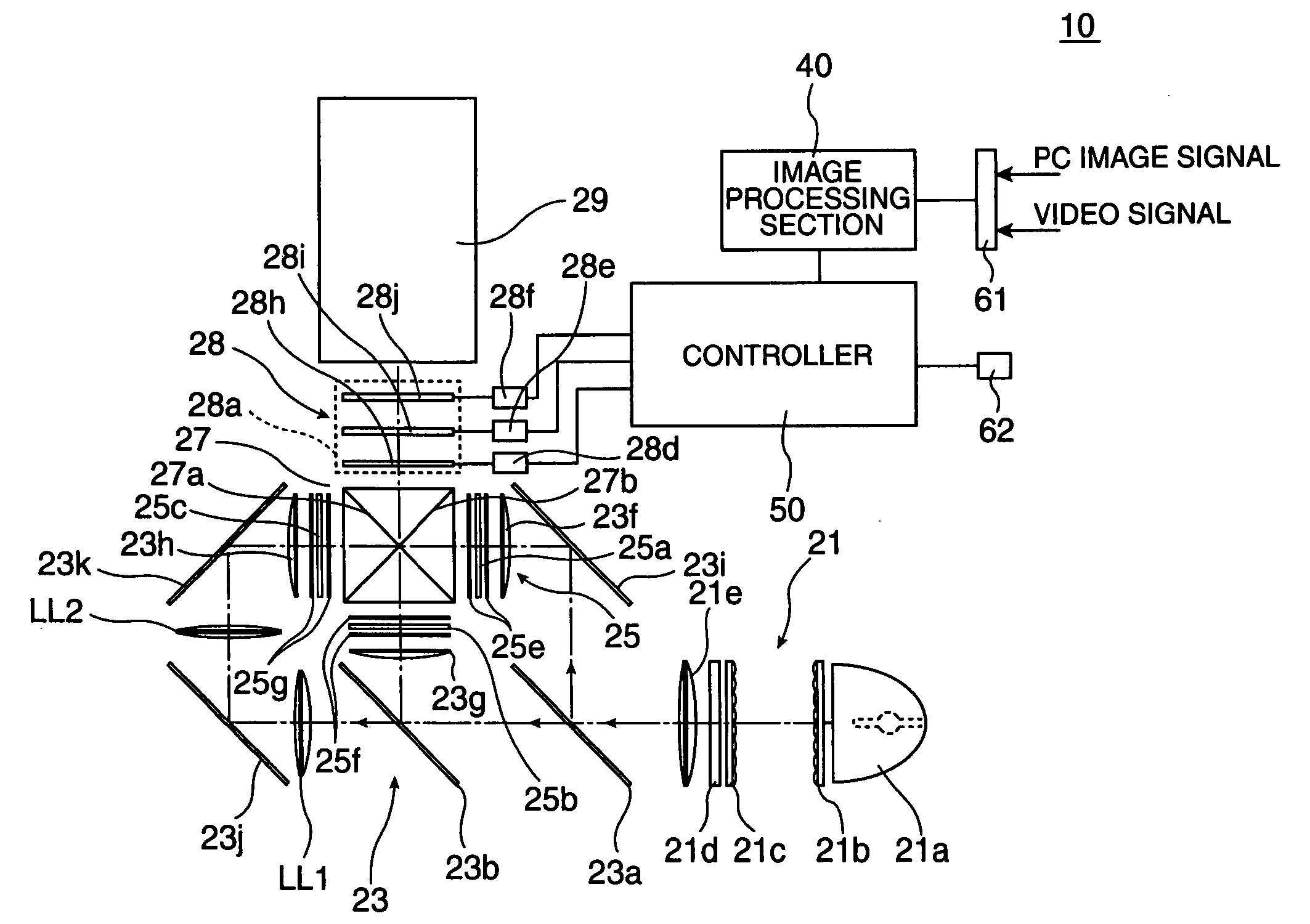
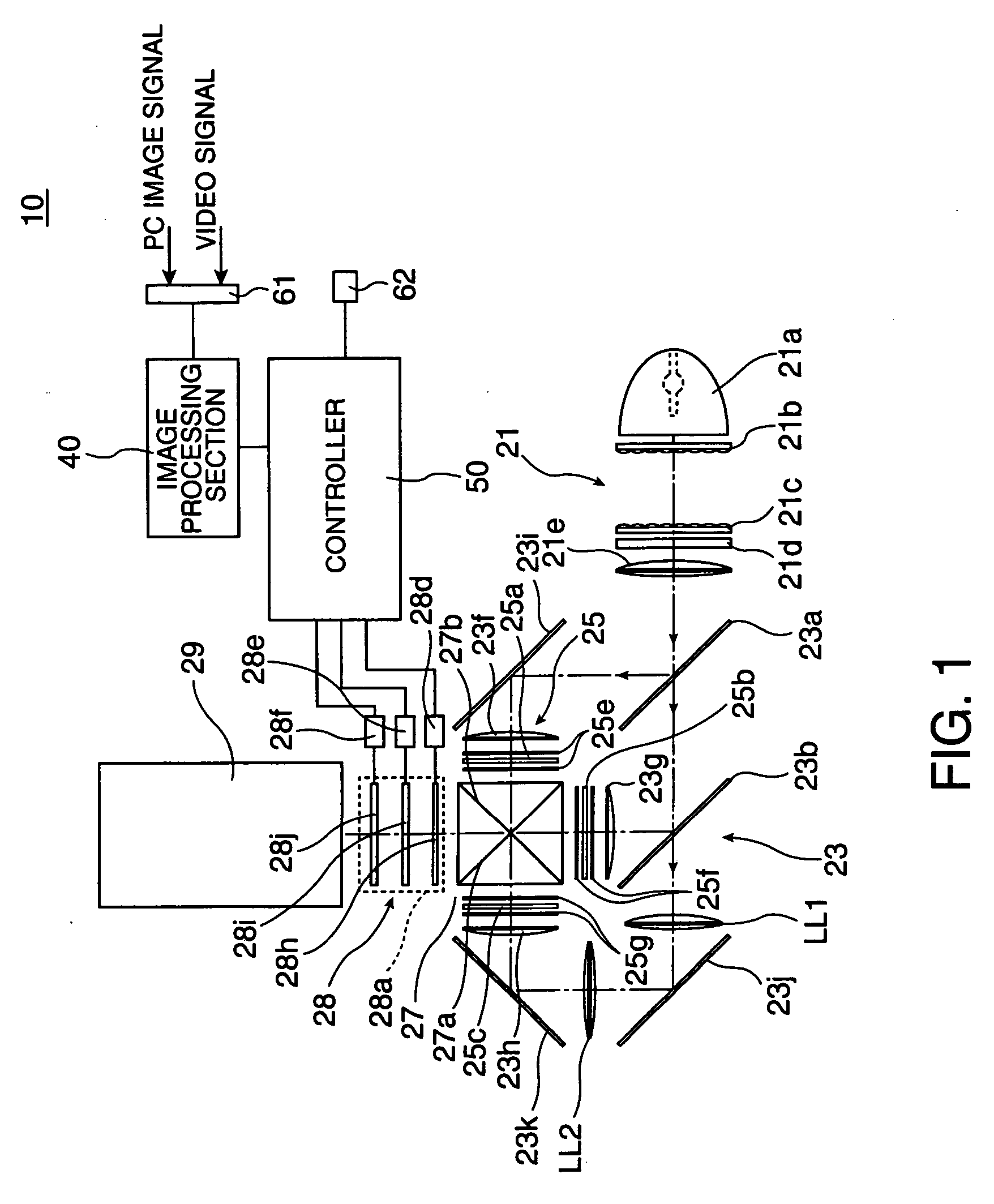
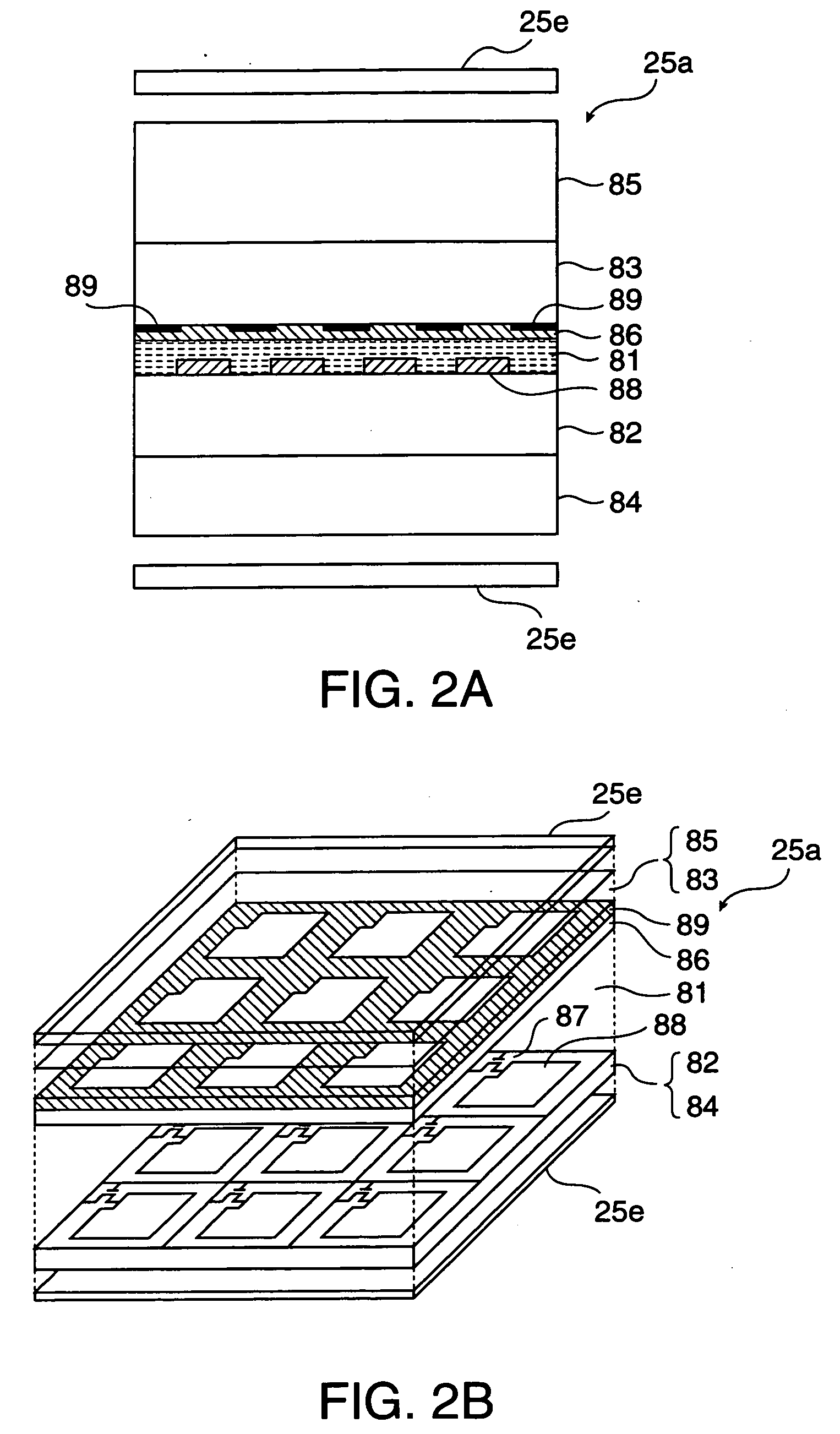
[0033]FIG. 1 is a schematic for explaining an optical system of the projector of the first exemplary embodiment mode. This projector 10 has a light source device 21 to generate light source light, a light division optical system 23 to divide the light source light from the light source device 21 into three colors of RGB, and a light modulating section 25 illuminated by illumination light of each color emitted from the light division optical system 23. The projector 10 also has a light synthesizing optical system 27 to synthesize image light of each color from the light modulating section 25, a BM removing unit 28 to perform one kind of optical low pass filter processing with respect to the image light synthesized by the light synthesizing optical system 27 in its operating state, and a projecting lens 29 as a pro...
second exemplary embodiment
Mode
[0053]FIG. 8 is a schematic for explaining a projector of a second exemplary embodiment mode. The projector of the second exemplary embodiment mode is formed by modifying the projector of the first exemplary embodiment mode. The same portions of the projector as the first exemplary embodiment mode are designated by the same reference numerals, and their overlapping explanations are omitted here. Further, portions particularly unexplained can be constructed similarly to those in the first exemplary embodiment mode.
[0054] In this case, the image light emitted from the liquid crystal light valves 25a, 25c for RB lights is set to S-polarized light vibrated in the direction perpendicular to the incident face perpendicular to both the dielectric multilayer films 27a, 27b. However, the image light emitted from the liquid crystal light valve 25b for G-light is set to P-polarized light vibrated within the above incident face. Therefore, the light source light taken out of the light sour...
third exemplary embodiment
Mode
[0059]FIG. 11 is a schematic for explaining a projector of a third exemplary embodiment mode. The projector of the third exemplary embodiment mode is formed by modifying the projector of the first exemplary embodiment mode. Portions particularly unexplained can be constructed similarly to those in the first embodiment mode.
[0060] This projector 110 has the BM removing unit 28 for each color of RGB at the first half stage of the cross dichroic prism 27. The black matrix area BA can be independently erased every each color of RGB by setting such a construction. Specifically, a various expression considering color characteristics can be also made since the ratio of branching light can be adjusted every each color of RGB and the shift amount of the branching light can be adjusted for each color of RGB. Actuators 28d to 28f (see FIG. 1) for operating the birefringent plates 28i, 28j and the λ / 2 phase difference plate 28h are arranged for each BM removing unit 28 although these actua...
PUM
 Abstract
Description
Claims
Application Information
 - R&D
- Intellectual Property
- Life Sciences
- Materials
- Tech Scout
- Unparalleled Data Quality
- Higher Quality Content
- 60% Fewer Hallucinations
Browse by: Latest US Patents, China's latest patents, Technical Efficacy Thesaurus, Application Domain, Technology Topic, Popular Technical Reports.
© 2025 PatSnap. All rights reserved.Legal|Privacy policy|Modern Slavery Act Transparency Statement|Sitemap|About US| Contact US: help@patsnap.com


