Moving camera stabilizer and stability control method thereof
A stable control method and technology for moving cameras, which can be applied to cameras, support machines, camera bodies, etc., and can solve the problem that the image is not the expected image
- Summary
- Abstract
- Description
- Claims
- Application Information
AI Technical Summary
Problems solved by technology
Method used
Image
Examples
Embodiment 1
[0035] Embodiment 1 (two-dimensional):
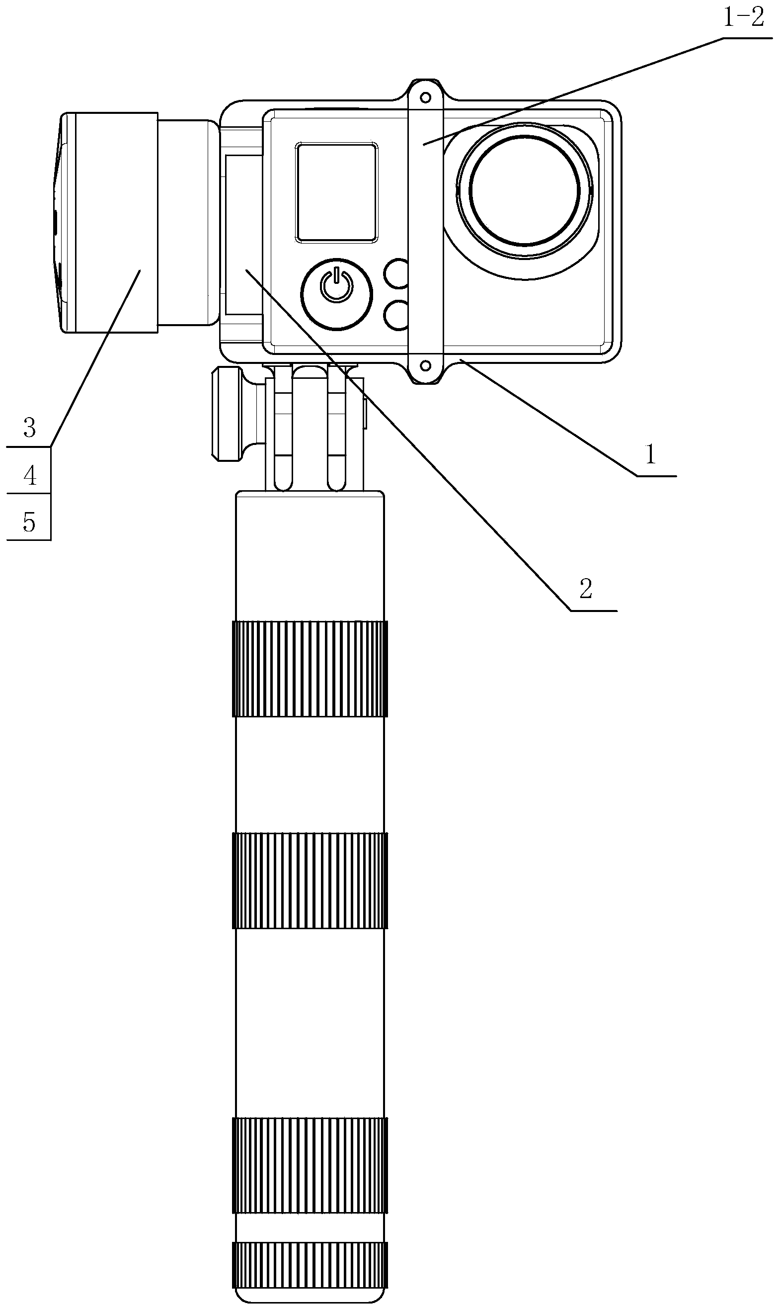
[0036] An action camera stabilizer such as figure 1 and 2 As shown, it mainly consists of a camera holder 1, a gyro sensor 2, a pitch motor 3, a pitch angle sensor 4, a pitch drive circuit 5, a pitch and roll motor 7, a connecting rod 6, a roll motor 7, a roll angle sensor 8, and a roll angle sensor 8. Roll drive circuit 9, fixed connecting rod 10, control upgrade circuit, button control circuit 11, power supply circuit 12 and battery 13 are formed.
[0037] The camera holder 1 is a frame structure, and the sports camera is fixed in the camera holder 1 . Described camera holder 1 is made of rear fixed frame 1-1, front fixed rod 1-2, upper fixed screw rod 1-3 and lower fixed screw rod 1-4. The rear fixed frame 1-1 is a back-shaped frame body, and the middle parts of the upper and lower sides of the rear fixed frame 1-1 are provided with mounting holes through the front and rear. The front fixed rod 1-2 is a straight rod shape, and th...
Embodiment 2
[0052] Embodiment 2 (three-dimensional):
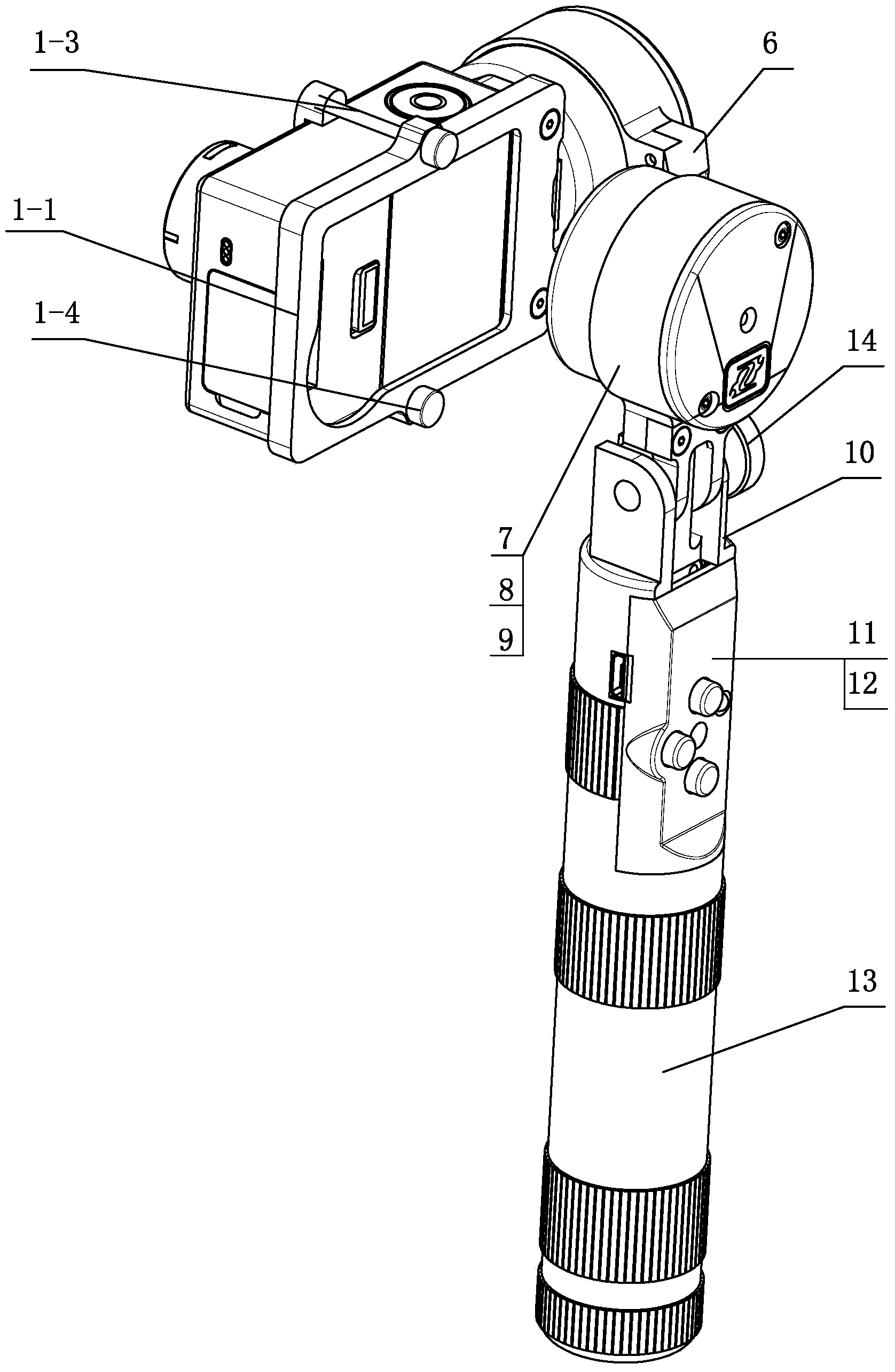
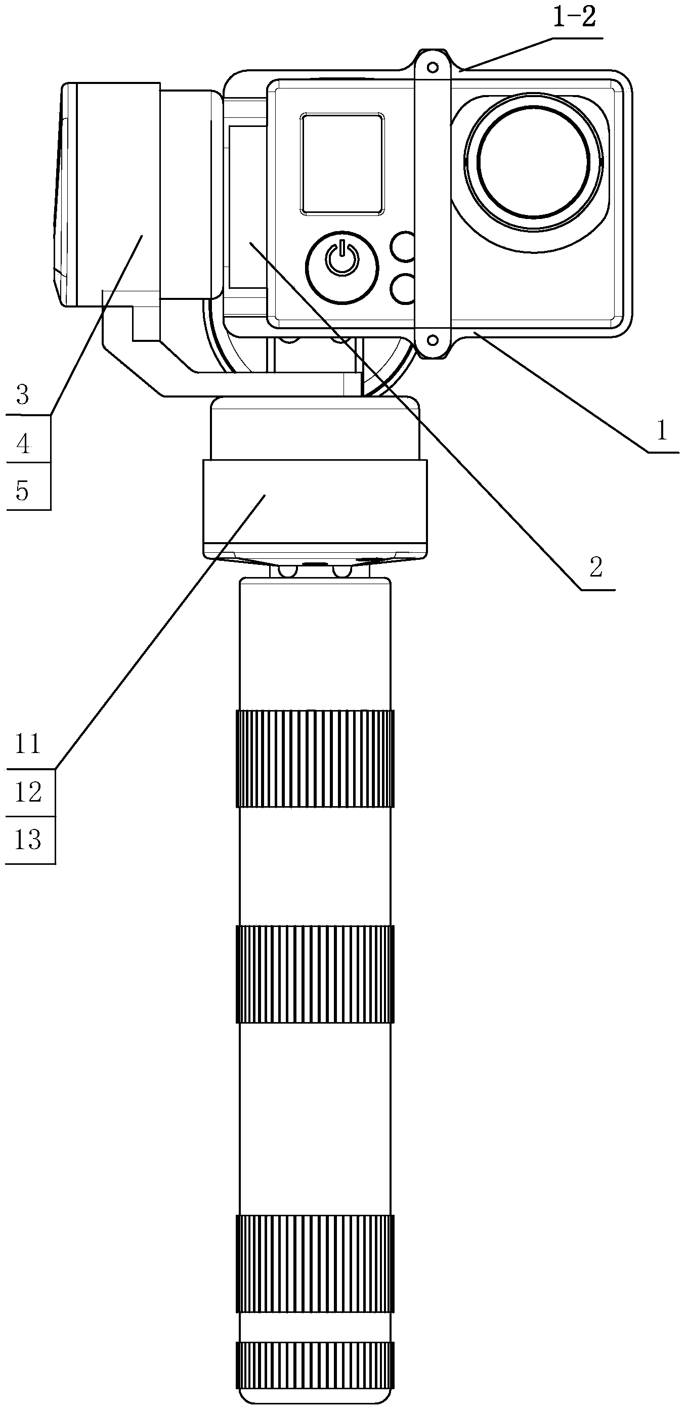
[0053] An action camera stabilizer such as figure 2 and 3 As shown, it mainly consists of a camera holder 1, a gyro sensor 2, a pitch motor 3, a pitch angle sensor 4, a pitch drive circuit 5, a pitch and roll motor 7, a connecting rod 6, a roll motor 7, a roll angle sensor 8, and a roll angle sensor 8. Rolling driving circuit 9, rolling and heading motor connecting rod, heading motor, heading angle sensor, heading driving circuit, fixed connecting rod 10, control upgrade circuit, button control circuit 11, power supply circuit 12 and battery 13.
[0054] The camera holder 1 is a frame structure, and the sports camera is fixed in the camera holder 1 . Described camera holder 1 is made of rear fixed frame 1-1, front fixed rod 1-2, upper fixed screw rod 1-3 and lower fixed screw rod 1-4. The rear fixed frame 1-1 is a back-shaped frame body, and the middle parts of the upper and lower sides of the rear fixed frame 1-1 are provided wit...
PUM
 Abstract
Description
Claims
Application Information
 - R&D
- Intellectual Property
- Life Sciences
- Materials
- Tech Scout
- Unparalleled Data Quality
- Higher Quality Content
- 60% Fewer Hallucinations
Browse by: Latest US Patents, China's latest patents, Technical Efficacy Thesaurus, Application Domain, Technology Topic, Popular Technical Reports.
© 2025 PatSnap. All rights reserved.Legal|Privacy policy|Modern Slavery Act Transparency Statement|Sitemap|About US| Contact US: help@patsnap.com


