
Exhaust system for enhanced reduction of nitrogen oxides and particulates from diesel engines

Inactive Publication Date: 2005-03-17
ENGELHARD CORP
View PDF21 Cites 82 Cited by
  • Summary
  • Abstract
  • Description
  • Claims
  • Application Information

AI Technical Summary

Benefits of technology

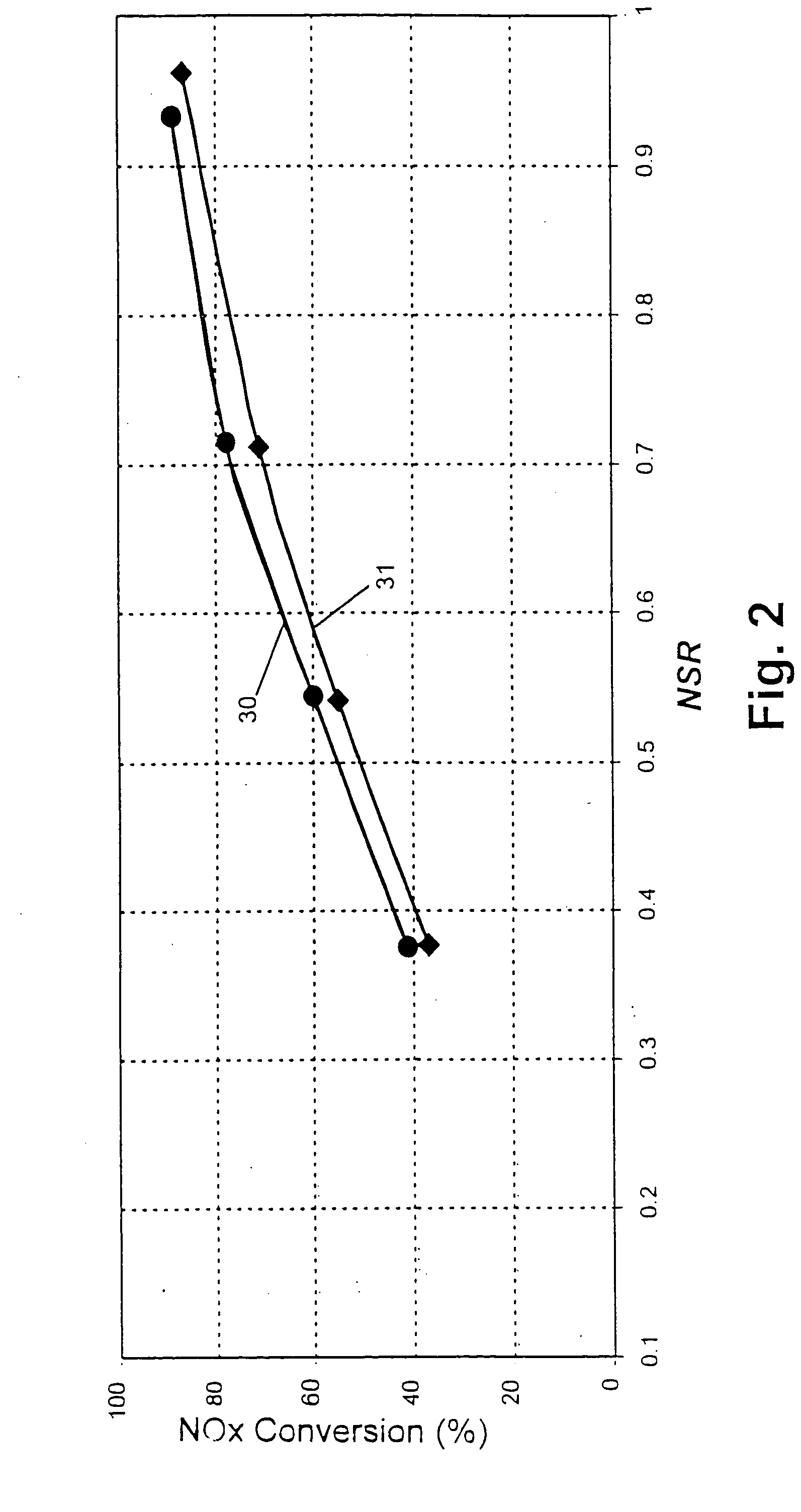
Accordingly, it is one of the major undertakings of this invention to provide an aftertreatment system configured with a Catalyzed Soot Filter (Pt / ZrO2-CeO2) up-stream of a zeolite (e.g. ZNX) SCR Catalyst to produce substantially better NOx conversion performance than the zeolite SCR Catalyst alone, especially for higher NSR (normalized stoichiometric ratio) levels of reductant and at lower exhaust temperatures.
Still another object of the invention is to provide a simple two part (filter & SCR) emission system sufficient to oxidize CO and HC, reduce the particulate emissions and reduce NOx emissions to N2. That is an oxidation catalyst (downstream of the SCR catalyst) is strictly speaking, not necessary to meet emission regulations. An oxidation catalyst may, however, be provided to insure against ammonia slip which is potentially possible under transient emission conditions. Such oxidation catalyst, if used, would be of smaller capacity than those conventionally used to oxidize ammonia slip occurring in conventional ammonia reductant systems.

Problems solved by technology

However, diesel exhaust is characterized by relatively high emissions of nitrogen oxides (NOx) and particulates.
Unfortunately diesel exhaust temperatures are many times considerably lower than that required for good catalyst efficiency (i.e., below “light-off”).
Unfortunately, one of the best, most stable, SCR catalysts, which is of the zeolite type (e.g. The assignee, Engelhard Corporation's ZNX catalyst, a Fe-Beta Zeolite), also has the highest optimum operating temperature.
As a result its effectiveness is greatly diminished at diesel exhaust temperatures of interest.
Unfortunately, the carbon soot particles require temperatures in excess of 500-550 EC to be combusted under oxygen rich (lean) exhaust conditions.

Method used


Image

  • Exhaust system for enhanced reduction of nitrogen oxides and particulates from diesel engines
  • Exhaust system for enhanced reduction of nitrogen oxides and particulates from diesel engines
  • Exhaust system for enhanced reduction of nitrogen oxides and particulates from diesel engines

Examples


Embodiment Construction

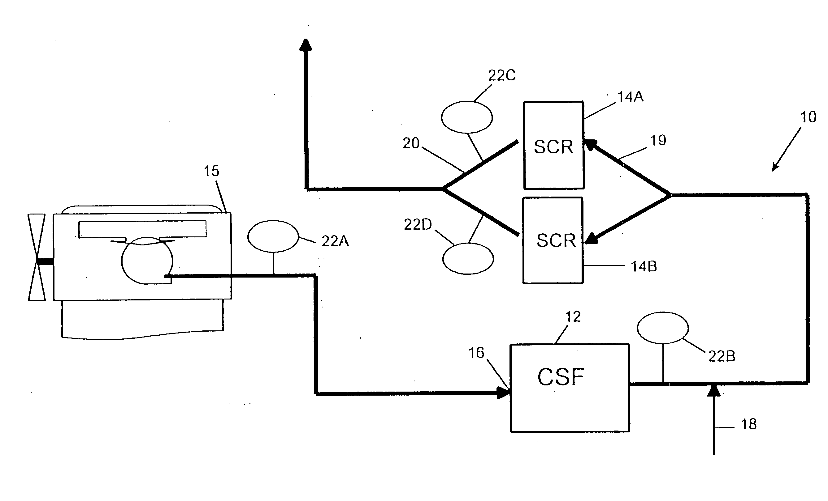
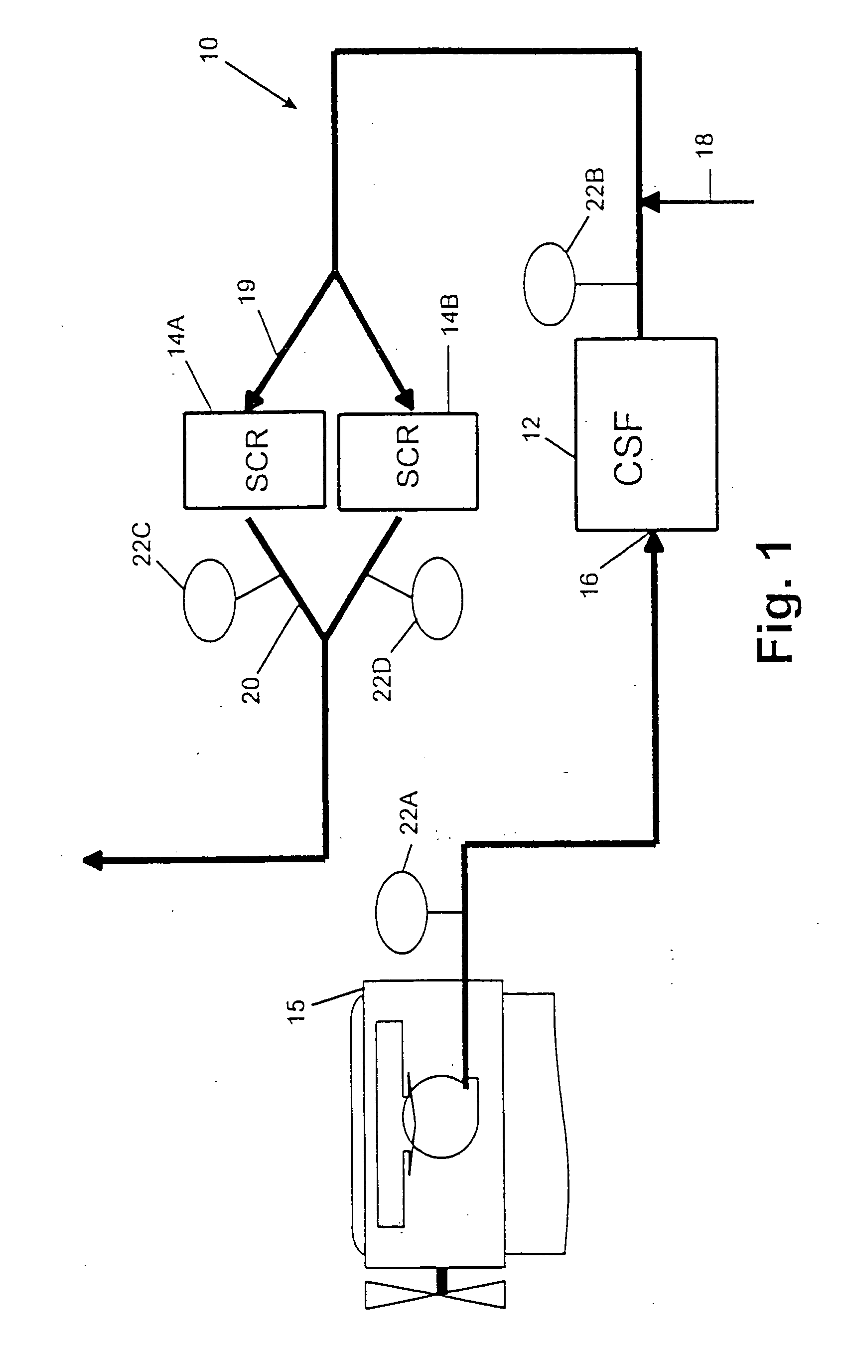
Referring now to the drawings where the showings are for the purpose of illustrating a preferred embodiment of the invention only and not for the purpose of limiting same, there is shown in FIG. 1 a bench test unit 10 which does not represent the commercial embodiment of the invention in its preferred embodiment. (The preferred embodiment is schematically illustrated in FIG. 14A.) The test unit 10 is shown in FIG. 1 because the unanticipated synergy between an up-stream CSF 12 and an SCR catalyst 14 was discovered via engine tests in an engine-dynamometer test cell depicted schematically in FIG. 1.

The engine 15 was a Model Year 1998 Caterpillar 3126 (7.2 liter) Direct Injected, Turbo-Charged / Intercooled engine rated at 300 HP @ 2200 RPM. For the purposes of the tests the engine was calibrated to produce 4 g / bhp-hr NOx emissions over the U.S. Heavy Duty Transient Test Cycle.

For the tests the fuel was an ultra-low sulfur (ULS) diesel fuel provided by Phillips Petroleum. This fuel...


PUM

PropertyMeasurementUnit
Fractionaaaaaaaaaa
Densityaaaaaaaaaa
Temperatureaaaaaaaaaa

Abstract

A diesel engine aftertreatment exhaust system uses catalyzed soot filters for particulate matter reduction and urea SCR catalysts for NOx reduction on diesel engines in a combined system to lower particulate matter and NOx at the same time. With this integral emission control system, diesel engines are able to meet ultra low emission standards.

Description

BACKGROUND A) Field of Invention. This invention relates generally to a diesel exhaust aftertreatment system and more particularly to a diesel exhaust treatment system that simultaneously provides for a high level reduction of nitrogen oxides (NOx) and particulate emissions under lean engine operating conditions. B) Incorporation by Reference. The following United States patents are incorporated by reference herein and made a part hereof. Specifically, the compositions of the catalysts disclosed in the patents below and how the compositions are made and / or applied to the disclosed filter or SCR catalysts are incorporated herein so that such material need not be repeated or explained again in detail in the Detailed Description of this invention. U.S. Pat. No. 4,833,113 to Imanari et al., issued May 23, 1989, entitled “Denitration Catalyst for Reducing Nitrogen Oxides in Exhaust Gas”; U.S. Pat. No. 4,961,917 to Byrne, issued Oct. 9, 1990, entitled “Method for Reduction of Nitrog...

Claims


Application Information

Patent Timeline
IPC IPC(8): F01N3/02B01D46/42B01D53/94F01N3/023F01N3/035F01N3/08F01N3/10F01N3/20F01N3/24F01N3/28F01N13/02F01N13/04
CPCB01D53/9409F01N13/0097B01D2255/20738B01D2255/50B01D2258/012F01N3/0231F01N3/035F01N3/2066F01N2510/06F01N2510/063F01N2610/02F01N2610/03F01N13/009F01N13/011B01D2251/2062Y02C20/10Y02A50/20Y02T10/12F01N3/023
Inventor KAKWANI, RAMESH M.VOSS, KENNETH C.PATCHETT, JOSEPH A.GRIMSTON, KARL R.
Owner ENGELHARD CORP
Learn More