
Monitor apparatus for computer system

a computer system and monitor technology, applied in the field of monitor apparatus for computer systems, can solve the problems of inconvenient use of conventional monitoring methods, affecting the execution efficiency of computers, and difficult to use system monitor software to display information without a proper monitor, etc., and achieve the effect of constant temperature and low nois

Inactive Publication Date: 2005-03-10
YANG CHIEN HSIN
View PDF1 Cites 36 Cited by
  • Summary
  • Abstract
  • Description
  • Claims
  • Application Information

AI Technical Summary

Benefits of technology

"The present invention provides a monitor apparatus for a computer system that can display system information without needing a monitor program. The monitor apparatus is connected to the computer motherboard and can display information related to the computer's operation, such as temperature and fan rotation speed. The system information is displayed on a screen on the monitor apparatus. The monitor apparatus can also generate alarms if abnormal temperatures or voltages are detected. Additionally, the monitor apparatus can control the computer's fans to achieve low noise and constant temperature. The monitor apparatus can also display multi-lingual debug code on its panel."

Problems solved by technology

The drawback of the conventional monitoring way is that, for the desktop computer, the user has to install the software first, and such software has to be executed every time when the computer system is booted.
The software seizures certain amount of the system resource, and thus affect the execution efficiency of the computer.
In addition, for small size industrial computer, it is difficult to use the system monitor software to display the information without a proper monitor.
According to the above, the conventional way for monitoring the computer system is inconvenient to use and requires further improvement.

Method used


Image

  • Monitor apparatus for computer system
  • Monitor apparatus for computer system
  • Monitor apparatus for computer system

Examples


Embodiment Construction

[0011] To further distinguish the characteristics and technical contents of the present invention, a detailed description accompanied with the above drawings is provided. It is appreciated that the accompanying drawings are only exemplarily references and do not restrict or limit the scope of the present invention.

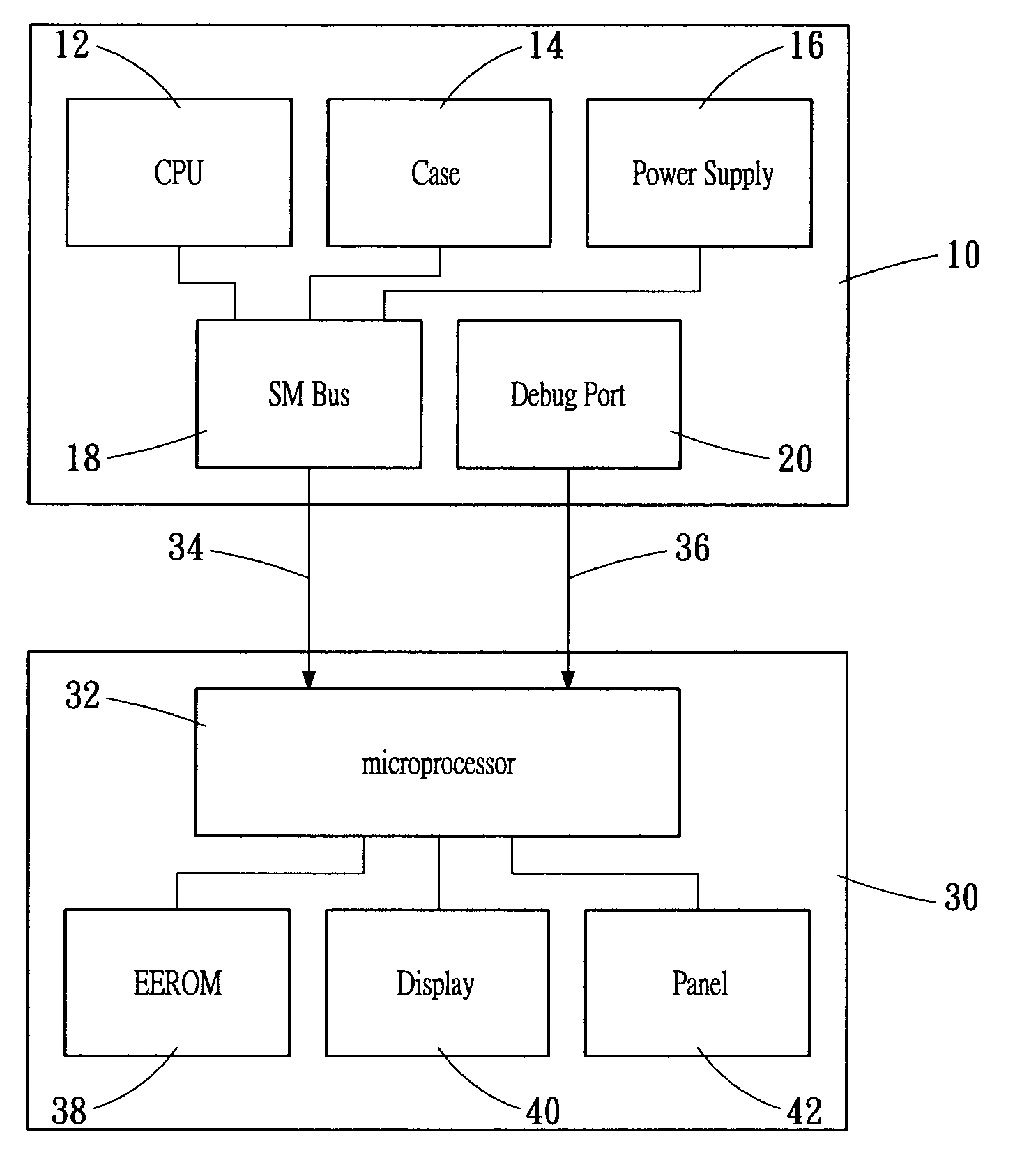
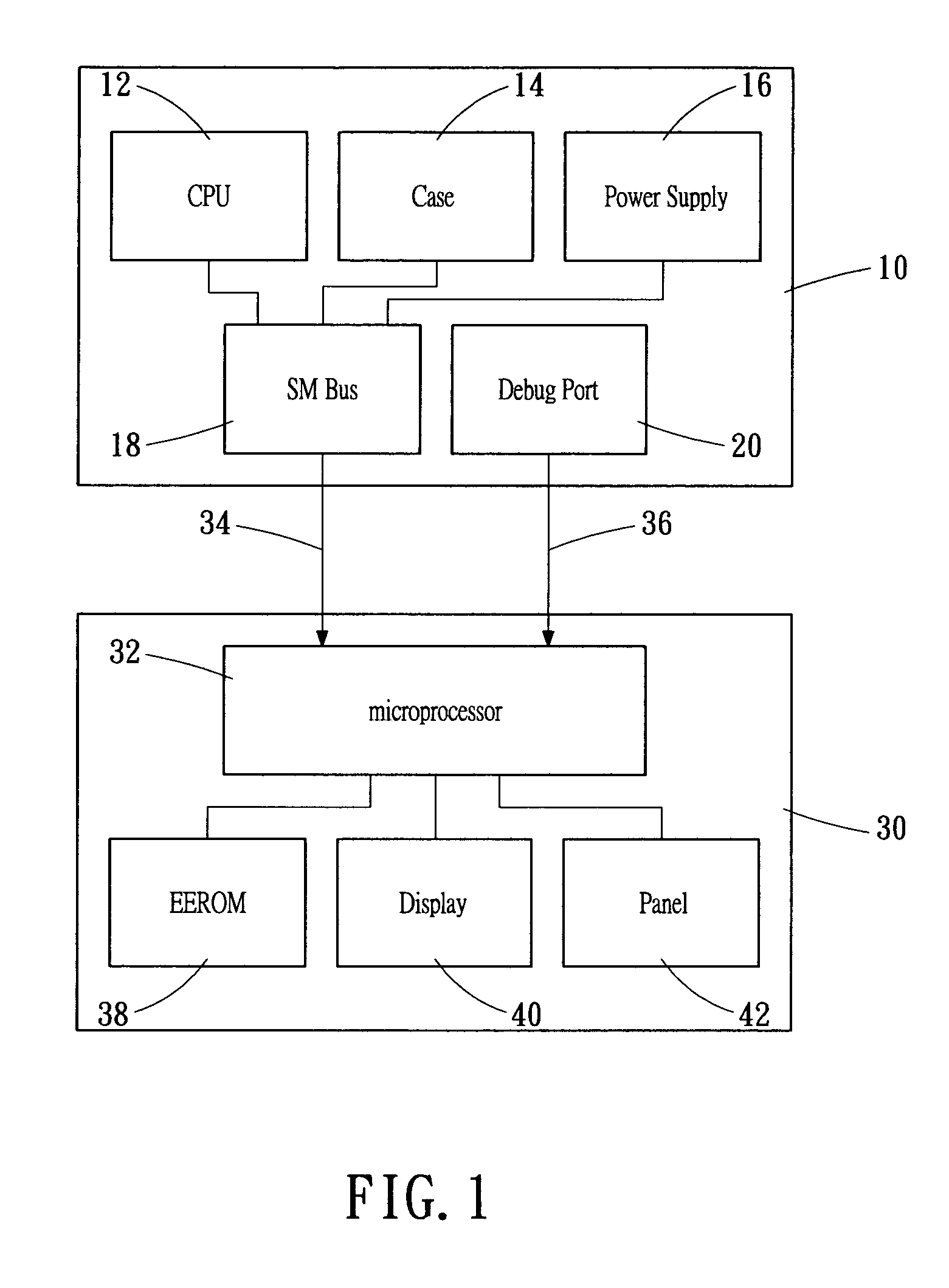
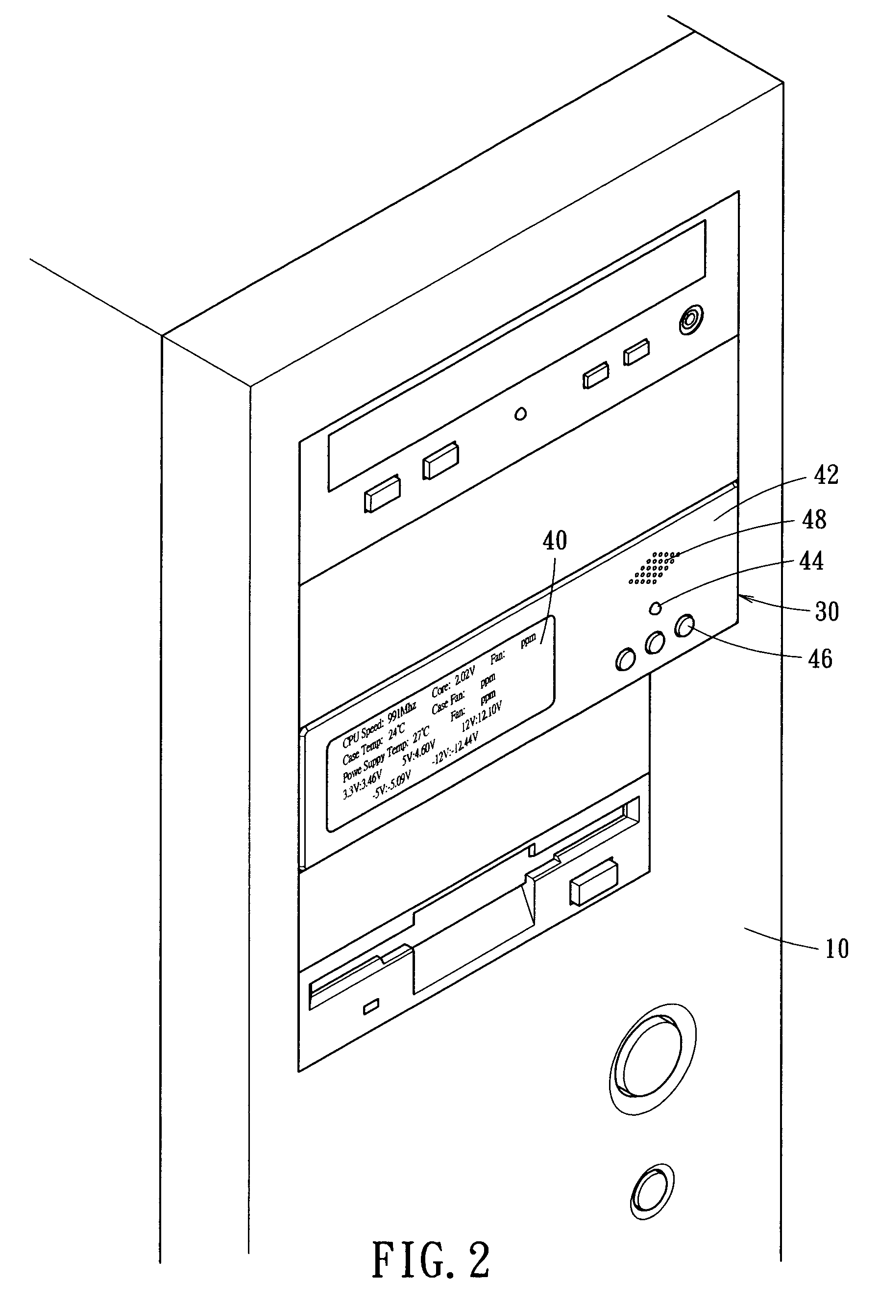
[0012] Referring to FIG. 1, a block diagram showing a monitor apparatus connected to a computer system is shown. The monitor apparatus 30 for a computer system includes a first microprocessor 32, a first input connection 34, a second input connection 36, an erasable memory 38, a display screen 40 and an operation panel 42. The computer host 10 connected to the monitor apparatus 30 comprises a central processing unit (CPU) 12, an enclosure 14, a power supply 16, a system management bus 18 and a debug port 20. The monitor apparatus 30 is installed in the computer host 10 as shown in FIG. 2.

[0013] The first connection 34 is connected to the system management bus (SMBus) 18 ...


PUM


Abstract

A monitor apparatus for a computer system, by connecting a system management bus (SMBus) of a computer motherboard, operating information such as operating temperature, voltage and fan rotating speed related to operation of the computer system is directly obtained through hardware. The operation information is displayed on a screen of the monitor apparatus. Thereby, the user can control the computer system in a stable condition according to the data displayed on the screen. When the above voltage or temperature is abnormal, a warning signal is generated. For example, a light emitting diode (LED) may be switched on to flash, or an alarm may be triggered to generate a beep.

Description

BACKGROUND OF THE INVENTION [0001] The present invention relates to a monitor apparatus for a computer system and, more particularly, to a monitor apparatus that provides real time system information related to operation of a computer system by hardware, so as to maintain the operation stability of the computer system. [0002] Computers have been an inevitable device in modern society. How to provide a stable operation during the continuous application of the computer system is important. Only when the real time operation information is available, the user can properly use the computer system and resolves the abnormality to avoid system down. [0003] The conventional way for monitoring the computer system is achieved by software. The user has to install the software into the computer first. Every time when the computer is booted, the software is executed to enter the system monitor program. The information related to the computer system such as operation temperature and voltage is the...

Claims


Application Information

Patent Timeline
Patent Type & Authority Applications(United States)
IPC IPC(8): G06F3/00G06F11/30G06F11/32
CPCG06F11/326G06F11/3058
Inventor YANG, CHIEN-HSIN
Owner YANG CHIEN HSIN
Learn More