
Write-once optical recording medium

Inactive Publication Date: 2005-03-10
KK TOSHIBA
View PDF5 Cites 48 Cited by
  • Summary
  • Abstract
  • Description
  • Claims
  • Application Information

AI Technical Summary

Benefits of technology

An object of the present invention is to provide a write-once optical recording medium capable of achieving a higher recording speed and a higher recording density.

Problems solved by technology

However, two serious problems remain unsolved in the write-once type optical disk.
One of the problems is that a limit of high-speed recording is being reached in the DVD-R drive that is available nowadays.
Therefore, if the groove is formed shallower for improving the sensitivity, it is impossible that the recorded marks produce a sufficiently high phase difference, leading to a low degree of the signal modulation.
It follows that read error for the data tends to be generated, resulting in failure to satisfy the DVD book standards.
It follows that the read error for the address data tends to be generated, resulting in failure to satisfy the DVD book standards.
The other problem to be noted is that a limit is being reached in data recording density for the DVD-R available nowadays.
It is very difficult to record a small mark with a high accuracy and to reproduce the recorded small mark by using a relatively large light spot.
As described above, it was difficult to satisfy both the higher recording speed and the higher recording density simultaneously in the conventional write-once optical recording medium such as a DVD-R.

Method used


Image

  • Write-once optical recording medium
  • Write-once optical recording medium
  • Write-once optical recording medium

Examples


example 1

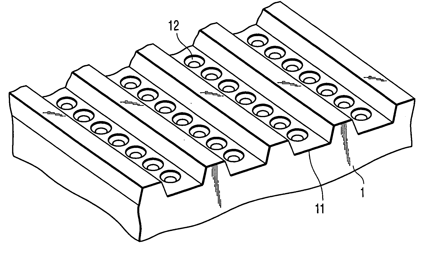
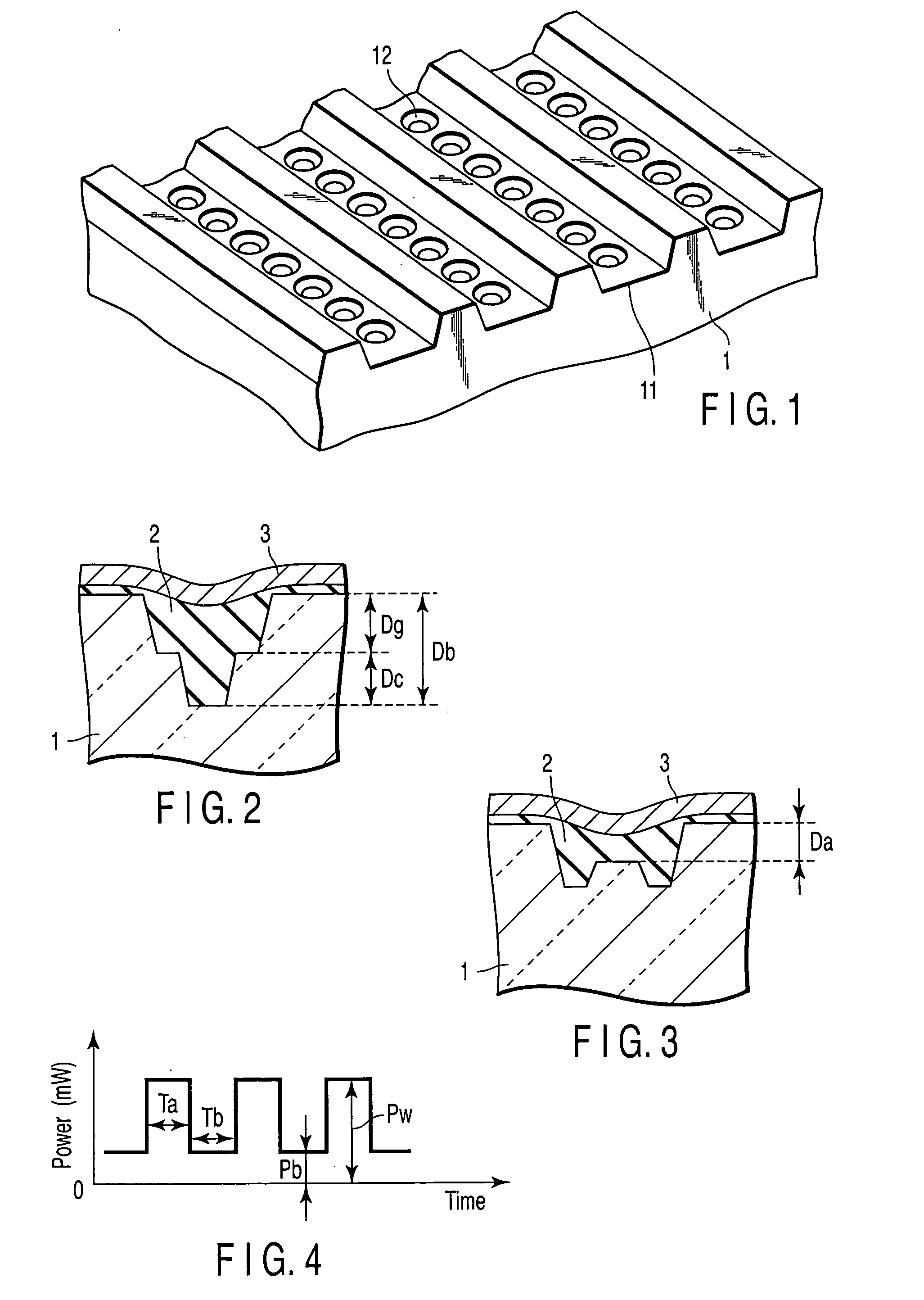
FIG. 1 is a perspective view of the polycarbonate disk substrate used for manufacturing the write-once optical recording medium (DVD-R) for this Example. As shown in the drawing, a spiral groove 11 is formed so as to provide a continuous step on the surface of the disk substrate 1, and recessed cells 12 forming discrete steps and each having a circular opening are formed within the groove 11. These cells 12 are regularly arranged at a prescribed pitch so as to form one line within the groove 11. The cells 12 define the recording region.

FIG. 2 is a cross sectional view showing the cell in the DVD-R for this Example before recording. The surface of the disk substrate 1 is coated with an organic dye forming a recording film 2 such that the dye fills the cells 12, and the recording film 2 is covered with a metal reflection film 3. FIG. 2 shows the groove depth Dg, the cell depth Dc, and the sum Db of Dg and Dc.

FIG. 3 is a cross sectional view of the cell in the DVD-R for this Example ...

example 2

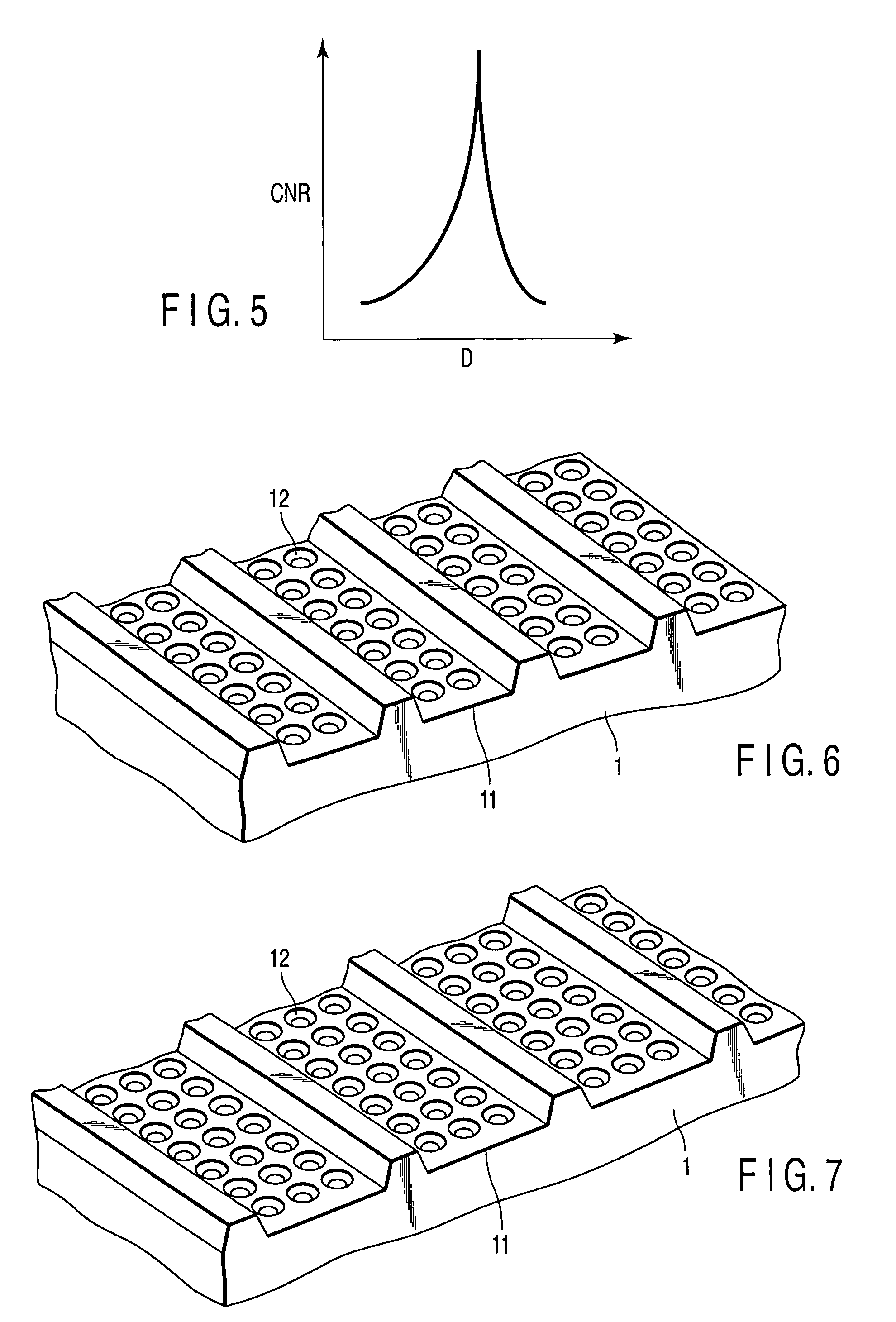
FIG. 6 is a perspective view of the polycarbonate disk substrate used for manufacturing the write-once optical recording medium (DVD-R) for Example 2. Example 2 differs from Example 1 in that the cells 12 were arranged in two lines within the groove 11.

In Example 2, the groove width was set at 90 nm, the track pitch (groove pitch) was set at 380 nm, the cell size was set at 40 nm, the interval between the adjacent cells was set at 40 nm, the groove depth Dg was set at 30 nm, and the cell depth Dc was set at 20 nm (Db=50 nm). In this case, the depth Da to the upper portion of the cell after recording was 18 nm, and the deformation amount D of the substrate within the cell caused upon recording was 32 nm. The write-once optical recording medium for Example 2 was equal to that for Example 1 in the other constructions.

The manufactured DVD-R was subjected to a recording-reproducing test using the optical disk evaluating machine equal to that used in Example 1.

Single frequency recor...


PUM


Abstract

A write-once optical recording medium has a transparent resin substrate having a concentric groove or a spiral groove and having recessed cells defining recording regions that are arranged in the groove, a recording film comprising an organic dye formed to fill the cells, and a metal reflection film formed on the recording film.

Description

CROSS-REFERENCE TO RELATED APPLICATIONS This application is based upon and claims the benefit of priority from prior Japanese Patent Application No. 2003-201130, filed Jul. 24, 2003, the entire contents of which are incorporated herein by reference. BACKGROUND OF THE INVENTION 1. Field of the Invention The present invention relates to a write-once optical recording medium capable of achieving a high recording density. 2. Description of the Related Art With spread of personal computers in recent years, importance of media for storing digital data is being enhanced. Recently, a recording medium capable of recording-reproducing digital data has come to be mounted to home electric appliances such as a digital video appliance in addition to a digital audio appliance. A recording medium for storing digital data has also come to be used in mobile appliances such as cellular phones. A disk-type medium, i.e., a recording disk, is widely used as such a recording medium because it permits...

Claims


Application Information

Patent Timeline
IPC IPC(8): G11B7/013G11B7/24G11B7/24067G11B7/244G11B7/246G11B7/248
CPCG11B7/24047Y10T428/21G11B7/248G11B7/24085
Inventor MORITA, SEIJISAKURAI, MASATOSHINAITO, KATSUYUKI
Owner KK TOSHIBA
Learn More