
System for high-resolution measurement of a magnetic field/gradient and its application to a magnetometer or gradiometer

a magnetic field/gradient and high spatial resolution technology, applied in the field of high spatial resolution measurement of magnetic field/gradient, can solve the problem of difficult positioning of the magnetometer very close to the skull

Inactive Publication Date: 2005-03-10
WU ZHEN
View PDF2 Cites 31 Cited by
  • Summary
  • Abstract
  • Description
  • Claims
  • Application Information

AI Technical Summary

Benefits of technology

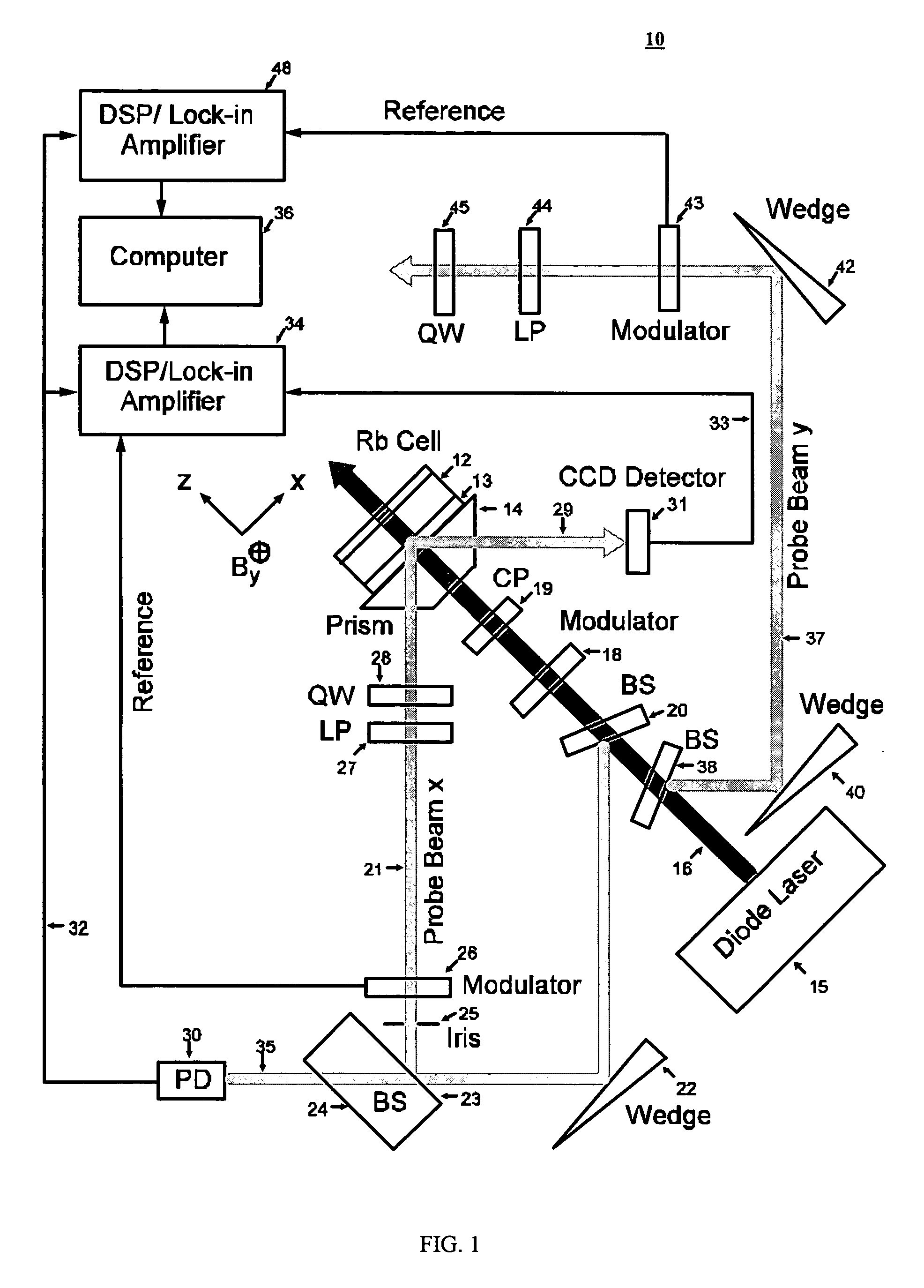
The system of the present invention can be used in medical imaging applications. In medical imaging applications, it is desirable to place the magnetometer to be very close to the skull since the magnetic field due to the brain activity is extremely weak. In conventional atomic magnetometers, the probe beam passes through the cell and the transmitted beam is monitored by a detector located on the other side of the cell. This geometric configuration makes it difficult to position the magnetometer very close to the skull. In the present invention, the reflected rather than the transmitted probe beam is monitored and consequently the probe beam and the detector are on the same side of the cell, which allows the magnetometer to be positioned very close to the skull.

Problems solved by technology

This geometric configuration makes it difficult to position the magnetometer very close to the skull.

Method used


Image

  • System for high-resolution measurement of a magnetic field/gradient and its application to a magnetometer or gradiometer
  • System for high-resolution measurement of a magnetic field/gradient and its application to a magnetometer or gradiometer
  • System for high-resolution measurement of a magnetic field/gradient and its application to a magnetometer or gradiometer

Examples


Embodiment Construction

Reference will now be made in greater detail to a preferred embodiment of the invention, an example of which is illustrated in the accompanying drawings. Wherever possible, the same reference numerals will be used throughout the drawings and the description to refer to the same or like parts.

FIG. 1 is a schematic diagram of system for high spatial resolution measurement of magnetic field or gradient 10 in accordance with the teachings of the present invention. Cell 12 contains an active medium. For example, cell 12 can contain cesium (Cs), or rubidium (Rb) or potassium (K) vapor and buffer gas or gasses. In one embodiment, cell 12 can be a Pyrex glass cell filled with a 87Rb isotope and about 100 Torr N2 gas. For example, cell 12 can have a cylindrical shape. A typical cell 12 can have a diameter of about 10 mm and a height of about 1 mm. Cell 12 can be operated at about 150° C. to maintain sufficiently high number density of the active medium.

Cell 12 can be coated with anti-rel...


PUM


Abstract

The present invention relates to a method and system for high spatial resolution measurement of a magnetic field or gradient. The method determines Zeeman polarization at a submicron distance from cell surfaces of an optical pumping cell using two laser beams. A strong pump beam produces Zeeman polarization in the vicinity of surfaces inside the optical pumping cell. The Zeeman polarization precesses around the magnetic field that is to be measured and is probed by the evanescent wave of a weak probe beam. The precessing Zeeman polarization can be monitored by measuring reflectivity of the probe beam at an interface between the active medium and the cell. The polarization can be used to measure the magnetic field or gradient. In one embodiment a second probe beam in the yz-plane is incident on the same position as the pump beam and the first probe beam that is in the xz-plane. Both probe beams undergo total internal reflection at an interface between the cell surface and the active medium. The reflectivities of the two probe beams are measured, from which the x, y and z components of the magnetic field can be determined simultaneously.

Description

BACKGROUND OF THE INVENTION 1. Field of the Invention The present invention relates to a system for high spatial resolution measurement of a magnetic field / gradient, such as submicron spatial resolution and its application to a magnetometer or gradiometer. 2. Description of Related Art The excitation of cells of atomic or molecular gases such as helium, rubidium or cesium, using a monochromatic light beam, is known and has been the object of a great many applications in many devices such as magnetometers. U.S. Pat. No. 5,503,708 describes a system for optical pumping of a cell of atomic or molecular gases having at least one resonance optical cavity containing a cell of atomic gases and a semiconductor laser generating an optical wave being coupled to the optical cavity. U.S. Pat. No. 4,088,954 describes a magnetometer transducer which includes a group of plated magnetic wires arranged in parallel physically and connected in series electrically to serve as a drive circuit, and ...

Claims


Application Information

Patent Timeline
Patent Type & Authority Applications(United States)
IPC IPC(8): G01R33/032
CPCG01R33/032A61B5/04008A61B5/245
Inventor WU, ZHEN
Owner WU ZHEN
Learn More