
Method for synchronizing processors in a multiprocessor system

Inactive Publication Date: 2005-03-03
HITACHI LTD
View PDF0 Cites 58 Cited by
  • Summary
  • Abstract
  • Description
  • Claims
  • Application Information

AI Technical Summary

Benefits of technology

[0015] The present invention has been proposed for solving the problems described above and an object of the present invention is, therefore, to provide a method of realizing the high-speed barrier synchronization among multiprocessors without execution of a process which requires a longer time just like the lock process and without addition of particular hardware mechanism.
[0019] Accordingly, the present invention can provide following effects for the synchronization process among multiprocessors in order to economically improve the parallel processing performance in the multiprocessor system.
[0022] Realization of the barrier synchronization processes in various scales described above means that necessary number of areas can be attained because the synchronization flag areas are provided on the main memory, for example, even when the number of processors which take part in the barrier synchronization increases remarkably. Moreover, such process can also be realized, even in the more practical barrier synchronization process, by increasing, as required, the number of times of check of the synchronization flag with the other processors through the control on the basis of the software.

Problems solved by technology

In addition, such exclusive process has disadvantage that the processing time remarkably increases as the number of processors for executing the barrier synchronization increases.
Particularly, when the barrier synchronization is often required, efficiency of parallel process will be remarkably lowered due to the influence of lock process and in some cases, high-speed process cannot be realized because of the serial execution.
Moreover, the former prior art also has a problem that memory access performance is lowered because the data read and write operations resulting from the lock process are conducted for only one address on the main memory.
In addition, the latter prior art has a problem that, although one processor is defined as the master processor and the other processors are defined as the slave processors and thereby synchronization between these processors can be ensured, synchronization cannot be assured among the slave processors because the counter of shared memory is utilized only for synchronization between the master processor and the slave processors, and high-speed operation cannot be realized when this method is adapted to the parallel process.

Method used


Image

  • Method for synchronizing processors in a multiprocessor system
  • Method for synchronizing processors in a multiprocessor system
  • Method for synchronizing processors in a multiprocessor system

Examples


Embodiment Construction

[0031] The preferred embodiments of the present invention will be described with reference to the accompanying drawings.

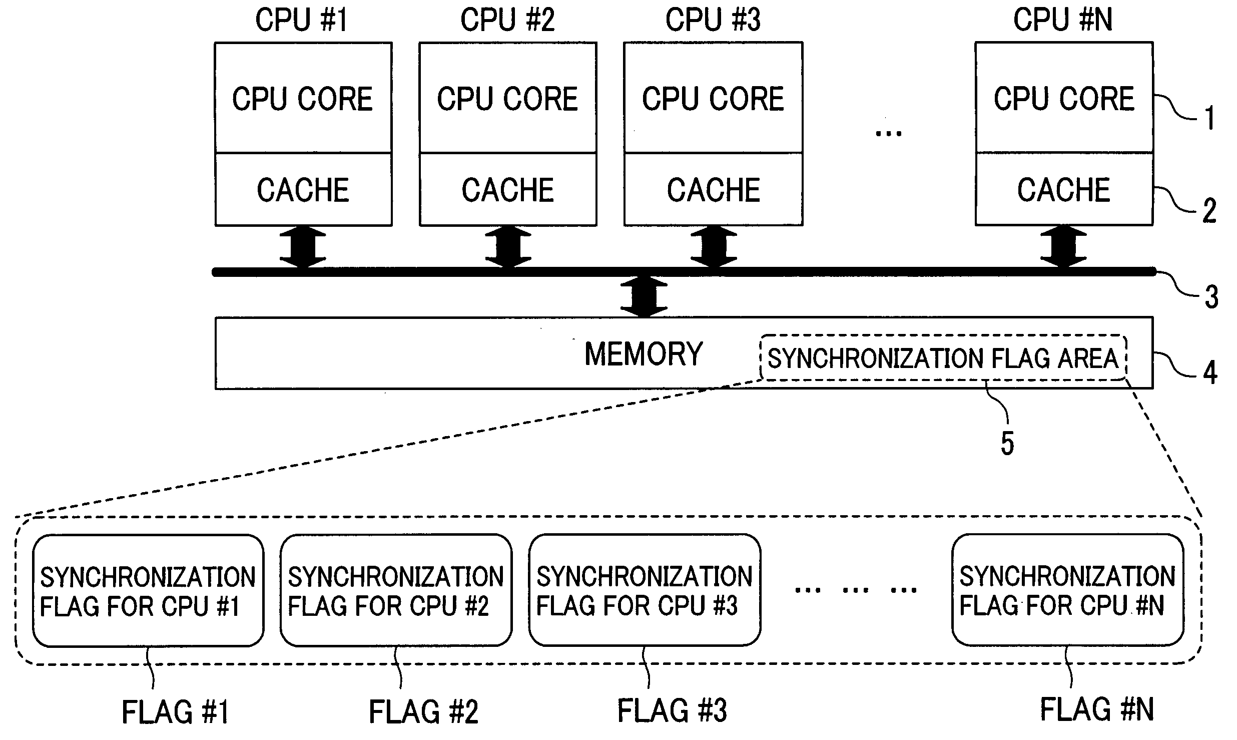
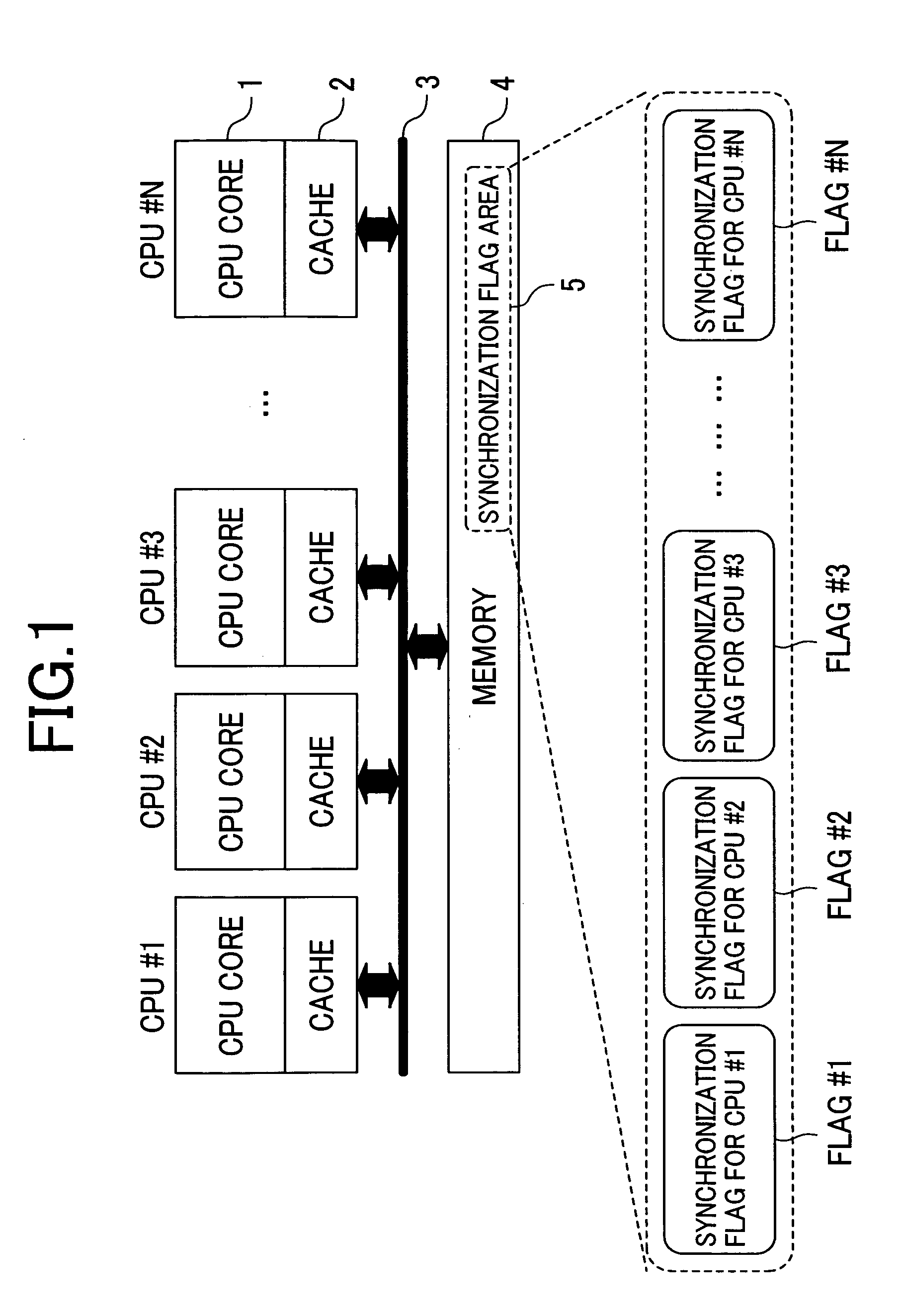
[0032]FIG. 1 illustrates a shared memory multiprocessor system to which the present invention is adapted.

[0033] In FIG. 1, a plurality of processors (CPU cores in the figure) are respectively provided with a cache memory 2. Moreover, the system comprises a common bus 3 for connecting each processor 1 with a memory (main memory) 4 and the main memory 4 which is used in common by a plurality of processors. In this case, the processor 1 is formed of CPU#1 to CPU#N.

[0034] In this embodiment, a partial area of the main memory 4 is defined as a synchronization flag area 5 used for barrier synchronization. The synchronization flag area 5 may be allocated to the desired area in the main memory 4 and therefore it is not required to prepare for the particular area for this synchronization flag area. Moreover, an area for barrier synchronization (battier point or timing) h...


PUM


Abstract

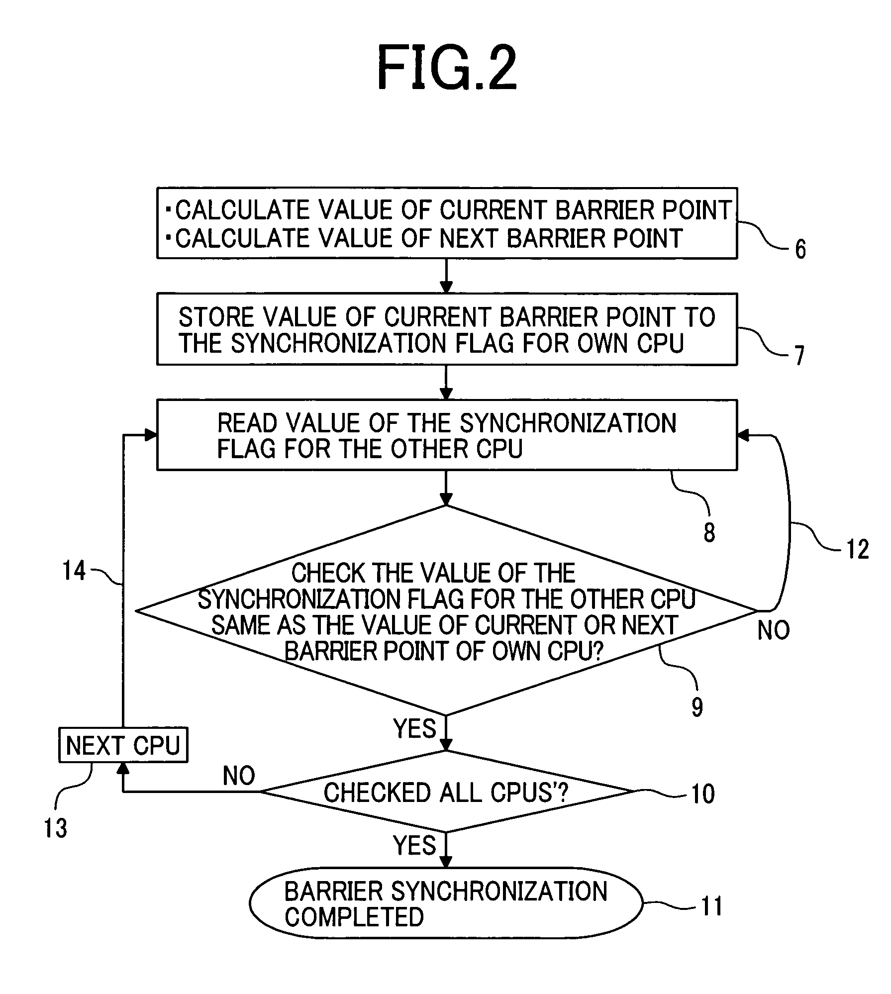
The high-speed barrier synchronization is completed among multiprocessors by saving overhead for parallel process without addition of a particular hardware mechanism. That is, the barrier synchronization process is performed by allocating the synchronization flag area, on the shared memory, indicating the synchronization point where the execution of each processor for completing the barrier synchronization is completed, updating the synchronization flag area with the software in accordance with the executing condition, and comparing, with each processor, the synchronization flag area of the other processors which takes part in the barrier synchronization.

Description

CLAIM OF PRIORITY [0001] The present application claims priority from Japanese application JP 2003-300510 filed on Aug. 25, 2003, the content of which is hereby incorporated by reference into this application. FIELD OF THE INVENTION [0002] The present invention relates to a multiprocessor system, and particularly to barrier synchronization process in a shared memory multiprocessor system and a method of controlling a computer for realizing barrier synchronization with an easier program code without necessity of exclusive hardware. BACKGROUND OF THE INVENTION [0003] Upon execution of parallel programs, barrier synchronization is required among processors in the shared memory multiprocessor system in which processors share the memory. [0004] In the prior art, the process called lock procedure has been executed in order to maintain coherence for such barrier synchronization. [0005] This process is intended to execute the exclusive access control for data and enables a plurality of proc...

Claims


Application Information

Patent Timeline
IPC IPC(8): G06F9/46G06F9/52G06F12/08G06F12/00G06F15/167G06F15/177
CPCG06F9/522G06F9/52
Inventor NAKAMURA, TOMOHIROSUKEGAWA, NAONOBU
Owner HITACHI LTD
Learn More