
Vehicle impact attenuation device

a technology of attenuation device and vehicle, which is applied in the direction of vehicle safety arrangment, bumper, way, etc., can solve the problems that devices cannot avoid accidents, reduce consequences, and only fulfill requirements

Inactive Publication Date: 2005-03-03
ROSSMANN MICHAEL
View PDF17 Cites 12 Cited by
  • Summary
  • Abstract
  • Description
  • Claims
  • Application Information

AI Technical Summary

Benefits of technology

"The invention proposes a device that reduces the impact of a vehicle crash by using two absorber bodies that transform impact energy into deformation energy. These bodies are arranged in pairs, with one body on either side of the central axis of the device. The absorber bodies are mechanically interconnected, so that when one body is deformed due to a crash, the other body is also deformed. This results in a more effective attenuation of the impact and reduces the risk of injury to occupants of the vehicle."

Problems solved by technology

Such devices cannot avoid accidents but they can reduce the consequences thereof.
This requirement however is only fulfilled if the length of the device is oversized.
For mobile devices such a length is not practicable, for stationary devices this is at least an eye-sore and finally also restricted.
However, this ideal situation is present only in less than 10% of accidents.
If the impact is excentric and / or inclined, an other important disadvantage appears besides the fact that the deceleration rate is less high: The absorber bodies not directly affected by the impact maintain largely their original shape while the affected bodies are heavily deformed.
It may then happen that it is catapulted into the traffic running nearby.

Method used


Image

  • Vehicle impact attenuation device
  • Vehicle impact attenuation device
  • Vehicle impact attenuation device

Examples


Embodiment Construction

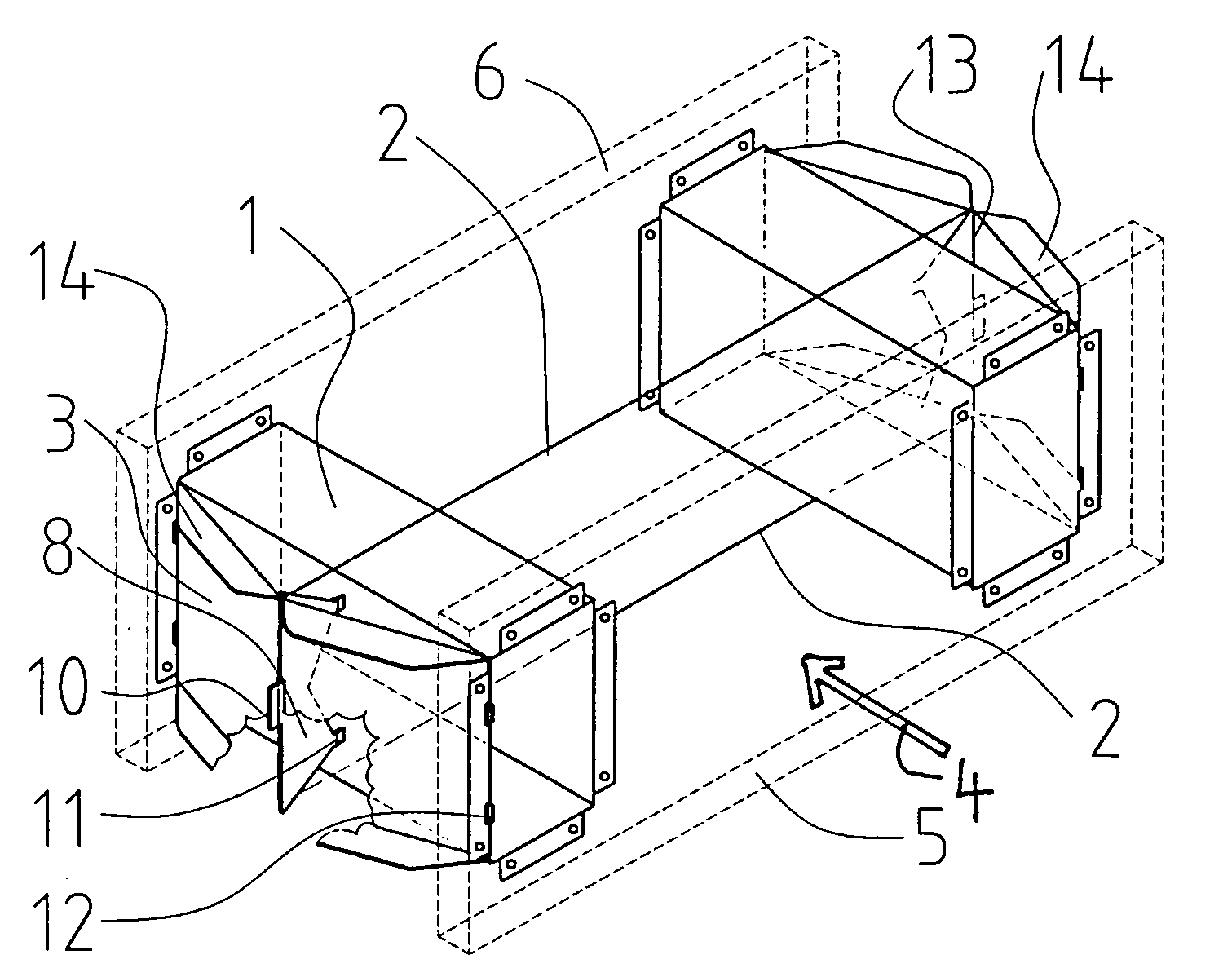
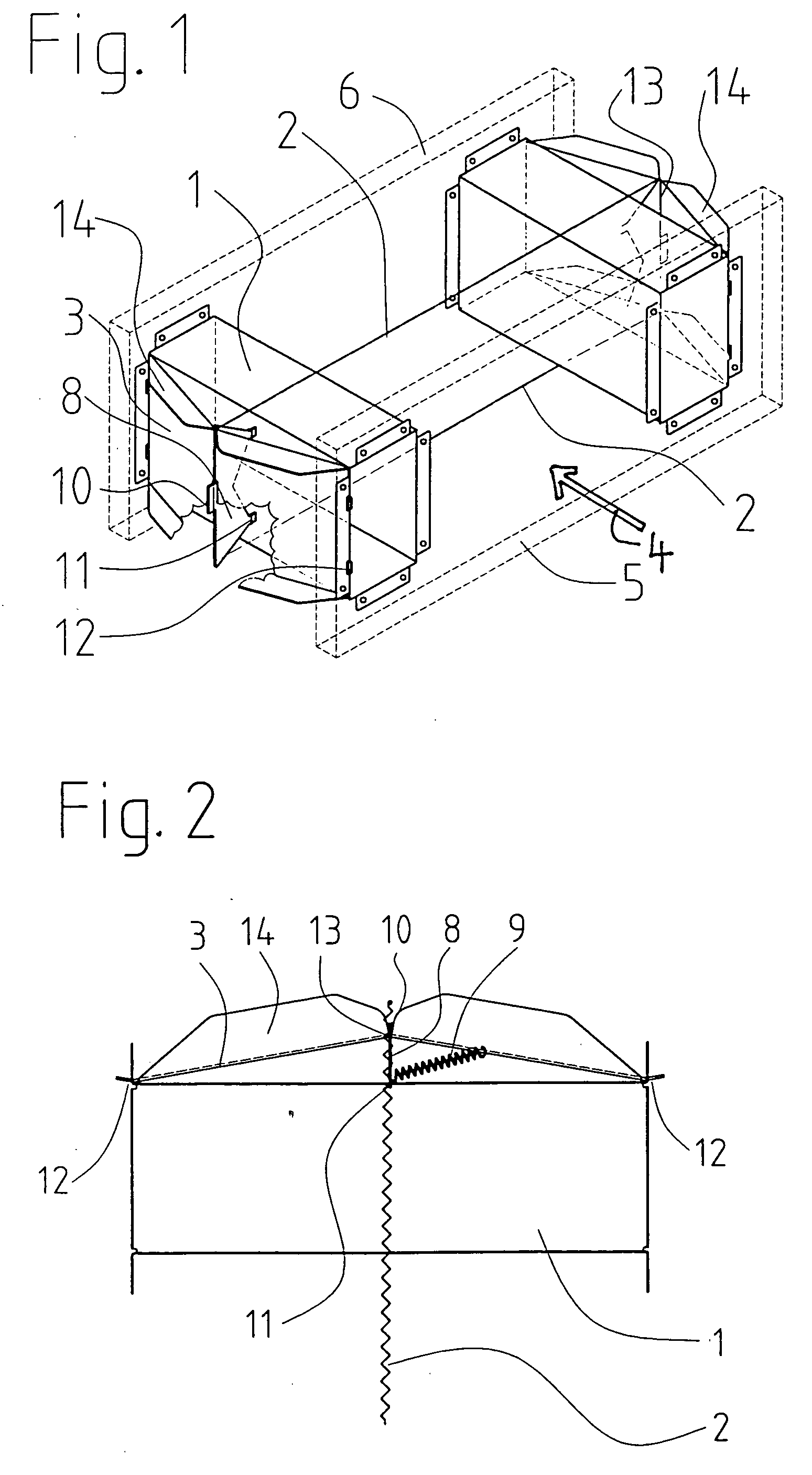
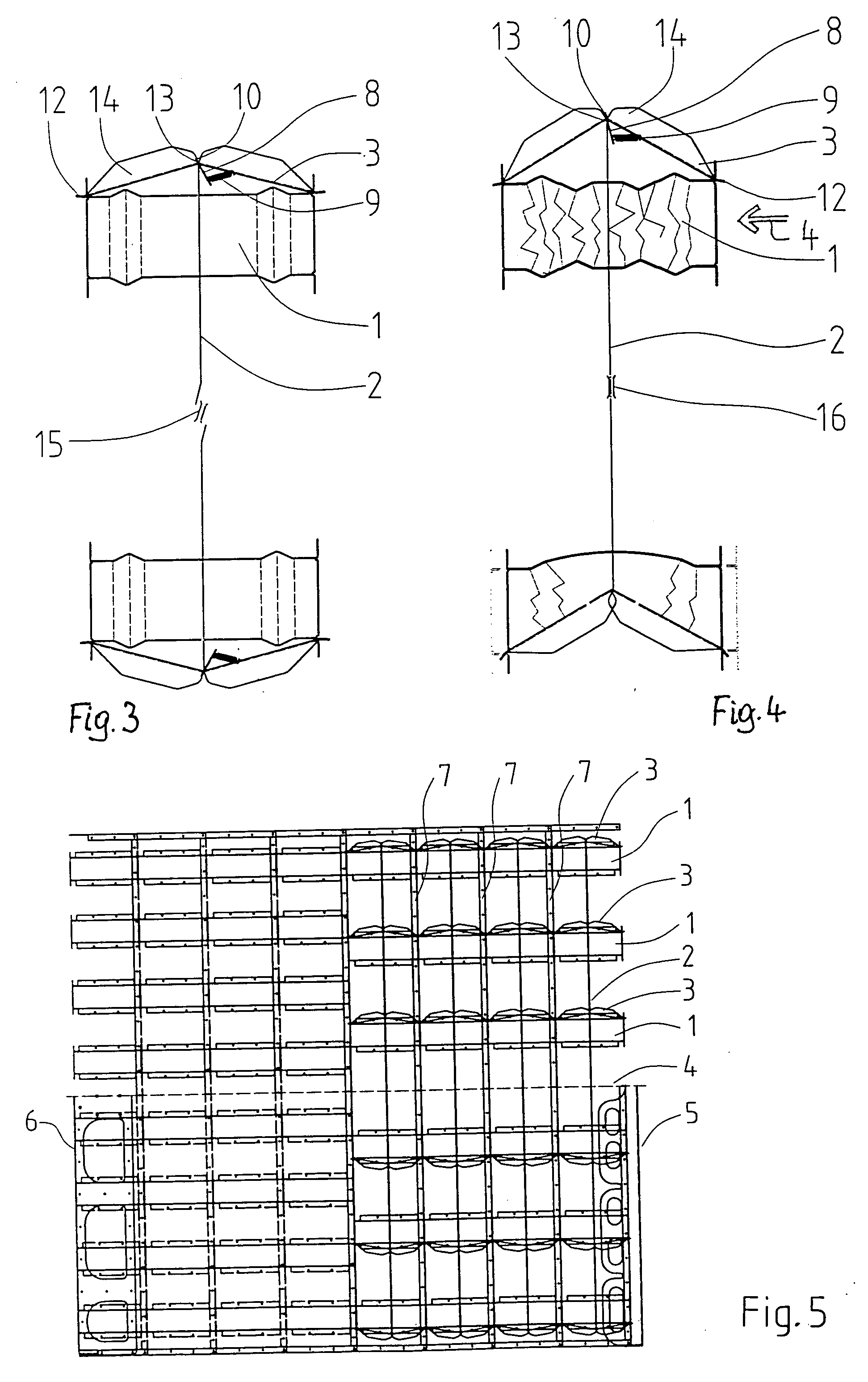
[0016]FIG. 1 shows two absorber bodies 1 disposed symmetrically on either side of a central axis and consisting each of a rigid metal box. Both boxes are fastened by screws, rivets or similar means to an impact plate 5 and a rear plate 6 (shown in interrupted lines). The rear plate is secured to the rear end of a heavy truck or to the ground. If the device, as it is common and shown in FIG. 5, comprises several rows of absorber bodies, the individual bodies are fixed by screwing or soldering to intermediate plates. In case of an impact the boxes are deformed and the distance between the impact plate and the rear plate and between the intermediate plates is reduced. The deformation energy produces a slowed-down absorption of the kinetic energy of the colliding vehicle. The shape and inner structure of the absorber body is not part of the present invention. The persons skilled in this art dispose of several variants for these bodies, all of them being compressed by the impact.

[0017] ...


PUM


Abstract

The vehicle impact attenuator comprises at least two impact absorber bodies for transforming impact energy which acts along a central impact axis, into deformation energy. The bodies are arranged in pairs, and the bodies of each pair are located on either side of a central axis of the device, and are mechanically interconnected in such a way that the deformation of one of these bodies due to a crashing vehicle results in a deformation also of the other absorber body, induced by said mechanical interconnection.

Description

BACKGROUND OF THE INVENTION [0001] The invention refers to a vehicle impact attenuation device according to the preamble of claim 1. Such an attenuator is known for example from U.S. Pat. No. 4,711,481. [0002] Vehicle impact attenuation devices are intended to improve security of the vehicle traffic by becoming deformed in a controlled manner when a vehicle hurts the device, thus destroying kinetic energy of the vehicle. There exist stationary vehicle impact attenuation devices, which are anchored at the ground, for example in front of a traffic divider, at the end of lateral crash barriers or in front of bridge piers, and mobile devices mounted at the rear end of heavy trucks for protecting temporary road works close to busy traffic. Such devices cannot avoid accidents but they can reduce the consequences thereof. [0003] In general, vehicle impact attenuation devices comprise a plurality of absorber bodies disposed in rows and columns, the bodies being deformed by an impact and thu...

Claims


Application Information

Patent Timeline
Patent Type & Authority Applications(United States)
IPC IPC(8): B60R19/00E01F15/14
CPCE01F15/148B60R2019/005
Inventor ROSSMANN, MICHAEL
Owner ROSSMANN MICHAEL
Learn More