
Deposition apparatus and manufacturing apparatus

a technology of manufacturing apparatus and evaporation apparatus, which is applied in the direction of vacuum evaporation coating, electroluminescent light source, coating, etc., can solve the problems of reducing throughput, limiting the application of evaporation apparatus to a large-sized substrate, and reducing the efficiency of utilizing expensive evaporation materials, etc., to achieve superior throughput and stable evaporation

Inactive Publication Date: 2005-02-17
SEMICON ENERGY LAB CO LTD
View PDF26 Cites 31 Cited by
  • Summary
  • Abstract
  • Description
  • Claims
  • Application Information

AI Technical Summary

Benefits of technology

[0016] An object of the present invention is to provide a manufacturing apparatus superior in terms of throughput and that have an evaporation source that can continue scattering a material in a stable state for a long time in a manufacturing apparatus carrying out evaporation.
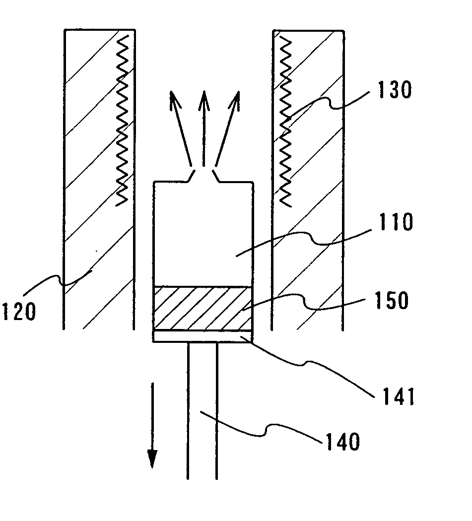
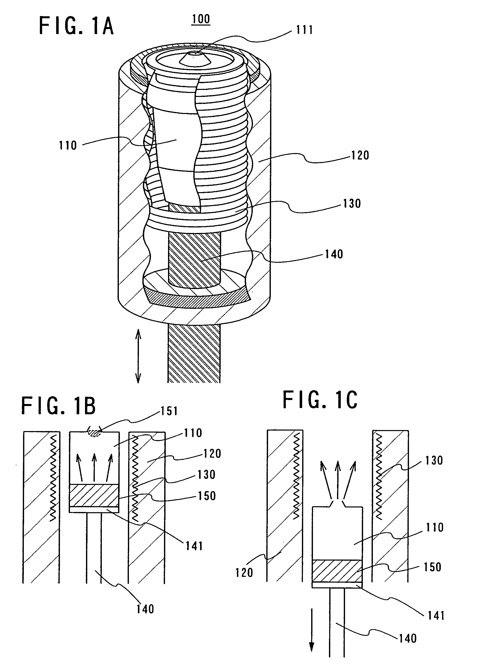
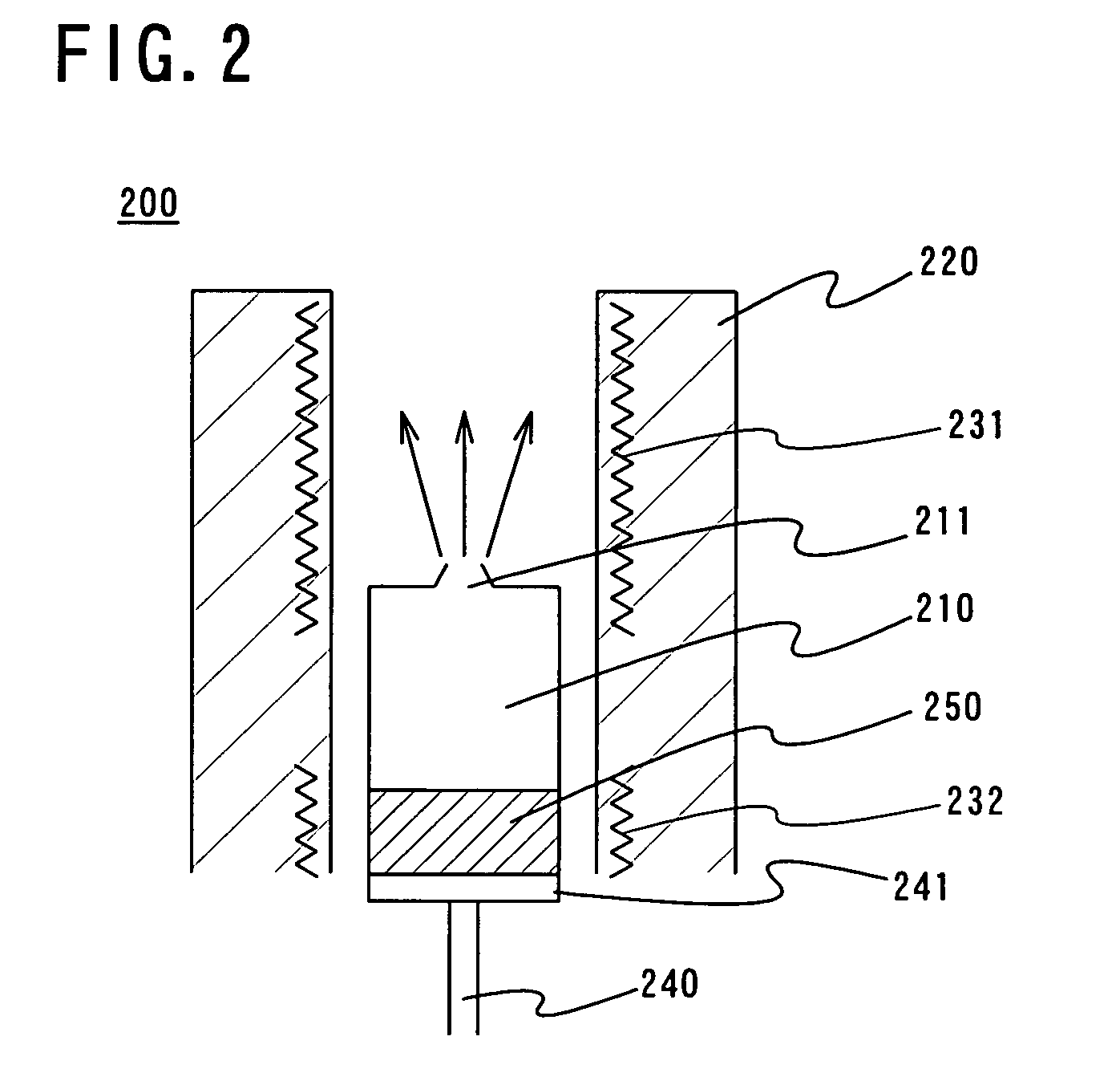
[0027] According to the invention, temperature of an evaporation material can be prevented from being lowered by the second heater; therefore, a crucible can be moved to a position of the upper first heater after dissolving the blockage; therefore, heating time can be shortened up to such a predetermined deposition rate.
[0033] A manufacturing apparatus according to the invention can use a filled material completely without exposing to an atmosphere as well as can dissolve blockage of an evaporation material in a deposition step of carrying out evaporation; therefore, it is a manufacturing apparatus superior in throughput that can carry out stable evaporation for a long time.

Problems solved by technology

Therefore, when a chamber is exposed to an atmosphere to exchange a material, a evaporation to form a film cannot be carried out for a long time and decreases a throughput, which are problems.
Therefore, there is a limitation to apply an evaporation apparatus to a large-sized substrate.
Therefore, during film formation of an EL layer, utilizing efficiency of the expensive evaporation material is quite low for about 1% or less and the manufacturing cost of the light-emitting device is extremely high.
However, deposition time per substrate gets longer for a large-sized substrate; therefore, there is high possibility that an evaporation material is run out during film formation.
Furthermore, throughput is decreased due to surplus heating time.
Thus, it is necessary to enlarge an evaporation container to be filled with a large amount of evaporation materials to evaporate for a long time.
Although such evaporation containers can be filled with quite large amount of evaporation materials, the thermal capacitance of the evaporation container and the evaporation material are large; therefore, temperature of the entire evaporation container tends to be uneven.
Compared to the bottom part of the evaporation container, temperature at the upper part thereof including an opening likely to be low since it is difficult to heat directly with a heater and a large amount of heat is escaped.
Then, once the evaporation particle is adhered, the particle continues to grow as a core, and lastly the opening of the evaporation container is clogged with the evaporation material and the evaporation material does not scatter; therefore, further film deposition is impossible, which is a problem.
However, there is a problem that the radiant heat escapes easily and the upper part of the evaporation container is unlikely to be heated since the upper part of the evaporation source is opened.
Therefore, there is a difference between temperature at the bottom part and the upper part of evaporation container, and the evaporated evaporation material is cooled at the upper part of the evaporation container, which generates a problem that the material clog at the opening.
Specifically, an evaporation material with high evaporation temperature is likely to generate temperature difference and evaporation is difficult.

Method used


Image

  • Deposition apparatus and manufacturing apparatus
  • Deposition apparatus and manufacturing apparatus
  • Deposition apparatus and manufacturing apparatus

Examples


example

[0065] A top view of a multi-chamber manufacturing apparatus is shown in FIG. 5. The manufacturing apparatus shown in FIG. 5 includes shutters 500a to 500n, a substrate loading chamber 520, a sealing and unloading chamber 519, transfer chambers 504 and 514, film formation chambers 506, 509, and 512, crucible installation chambers 526a to 526d, a pretreatment chamber 503, a sealing substrate loading chamber 517, and a sealing chamber 518. Note that the film formation chamber 506 may compose a plurality of chambers, which enables to separately use the chambers by a layer of an organic EL element in this case.

[0066] Hereinafter, a process for manufacturing an organic El element is described. A substrate is set at the substrate loading chamber 520. As a kind of a substrate, glass, plastic, or the like is used, of which size is 320 mm×400 mm, 370 mm×470 mm, 550 mm×650 mm, 600 mm×720 mm, 680 mm×880 mm, 1000 mm×1200 mm, 1100 mm×1250 mm, and a further large-sized substrate sized 1150 mm×13...


PUM

PropertyMeasurementUnit
widthaaaaaaaaaa
sizeaaaaaaaaaa
sizeaaaaaaaaaa

Abstract

An object of the present invention is to carry out stable film deposition for a long stretch of time without an evaporation material being stuck in a manufacturing apparatus that carries out evaporation. A driving portion that can move a crucible up and down is provided for an evaporation source of an evaporation apparatus. When the opening of the crucible is clogged with the evaporation material, the crucible is moved down and sealed in the evaporation source. The heater of the evaporation source can heat the opening efficiently; therefore, the evaporation material with which the opening is filled is evaporated; therefore, the blockage can be dissolved. Thereafter, the crucible is moved above and heated to carry out evaporation. It is possible to carry out film deposition without exposure to the atmosphere for a long stretch of time, which can improve the productivity of an organic EL element.

Description

BACKGROUND OF THE INVENTION [0001] 1. Field of the Invention [0002] The present invention relates to a manufacturing apparatus equipped with a deposition apparatus in an evaporation step of carrying out deposition by vaporizing a material (hereinafter, referred to as an evaporation material). [0003] 2. Description of the Related Art [0004] In recent years, research on a light-emitting device having an electroluminescence element (hereinafter, referred to as an EL element) as a self-luminous type light-emitting element is advanced. Especially, an EL element having an organic compound is also referred to as organic EL or an organic light emitting diode (OLED). The light-emitting devices using these elements have properties such as high response speed appropriate for an animation display, driving with low voltage or low power consumption; therefore, the devices are widely drawn attention as a next-generation display, especially as a flat panel display as well as a new-generation cellul...

Claims


Application Information

Patent Timeline
Patent Type & Authority Applications(United States)
IPC IPC(8): C23C14/12C23C14/24C23C14/26C23C16/00H05B33/10
CPCC23C14/12C23C14/26C23C14/246C23C14/243
Inventor OHARA, HIROKI
Owner SEMICON ENERGY LAB CO LTD
Learn More