
Adhesive cord cover

a cord cover and adhesive technology, applied in the field of decorative cord covers, can solve the problems of multiple cords becoming entangled with one another, electrical cords are not aesthetically pleasing, and may not meet similar aesthetic problems, so as to preserve adhesive properties

Inactive Publication Date: 2005-02-10
CLARK KIM MARIE
View PDF26 Cites 11 Cited by
  • Summary
  • Abstract
  • Description
  • Claims
  • Application Information

AI Technical Summary

Benefits of technology

[0010] It is an object of the invention to provide a cord cover that can be readily applied around a cord, such as an electrical cord, a cable, a telephone line, or a chandelier chain.
[0011] It is another object of the invention to provide a cord cover that is easier and less expensive to manufacture than prior art cord covers.
[0012] It is yet another object of the invention to provide a cord cover that can be adjusted to various diameters along its length, so as to cover an object that varies in diameter along its length.
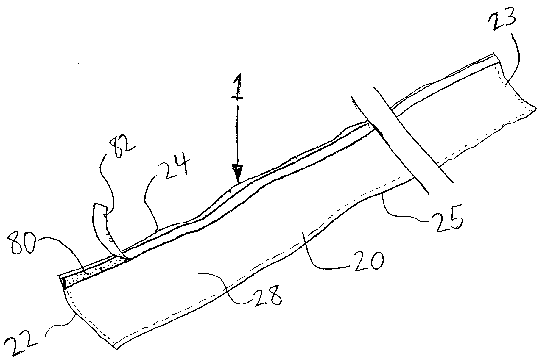
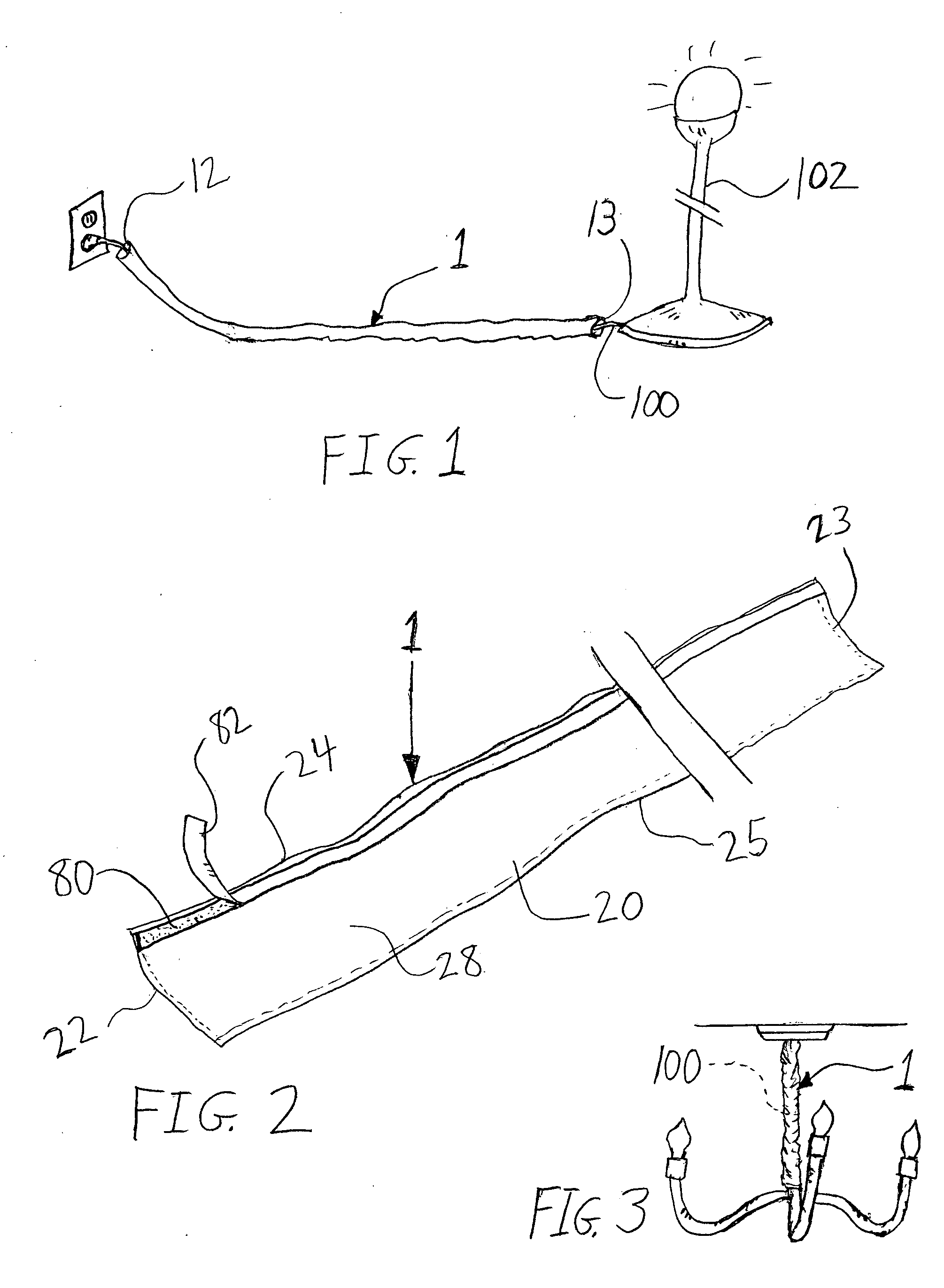
[0015] The pressure sensitive adhesive is preferably an adhesive transfer tape. The transfer tape preferably has a removable liner on the fastening side. The removable liner assists in preserving the adhesive properties of the pressure sensitive adhesive prior to use. The pressure sensitive adhesive transfer tape is preferably a continuous strip that extends substantially along the entire length of the piece of fabric.

Problems solved by technology

The electrical cord is not aesthetically pleasing.
Similar aesthetic problems are encountered with chandelier chains, which extend downward from a ceiling and include an electrical cord, which is typically intertwined with the chain.
Additionally, multiple cords may become entangled with one another.
The foregoing problems occur not only with electrical cords, but also with other types of plug-in cords and lines that carry data, such as telephone lines, coaxial cables, and the like.

Method used


Image

  • Adhesive cord cover
  • Adhesive cord cover
  • Adhesive cord cover

Examples


Embodiment Construction

[0022] In the following detailed description of the preferred embodiments, reference is made to the accompanying drawings which form a part hereof, and in which are shown by way of illustration specific embodiments in which the invention may be practiced. It is to be understood that other embodiments maybe utilized and structural changes maybe made without departing from the scope of the present invention.

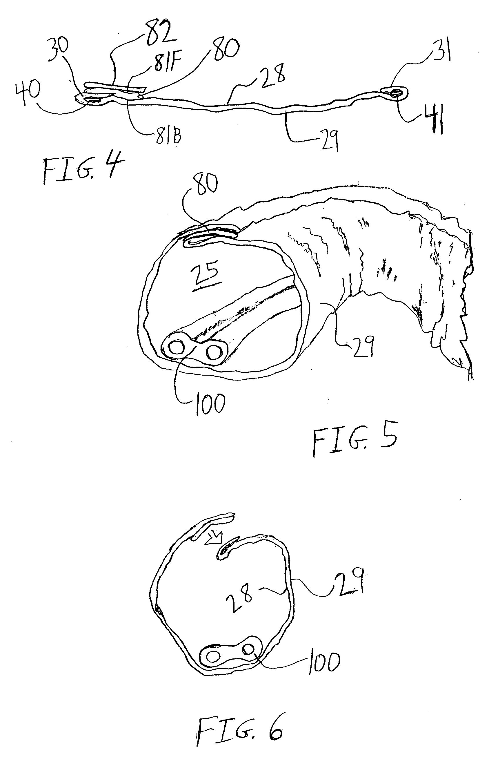
[0023] As shown in FIGS. 1 and 3, the invention is an adhesive cord cover device 1 for use in enveloping a linear object 100, such an electrical cord, a cable, telephone lines, a chandelier chain, a rod, a pipe, or the like, primarily for decorative purposes. Although the cord cover 1 is designed primarily for covering cords, it can also be used to cover other linear objects such as pipes, ceiling fan poles, curtain rods, shower curtain rods, closet rods, sides of bed frames and recliner chair handles.

[0024] As shown in FIG. 2, the adhesive cord cover 1 is formed from a lengthwis...


PUM

PropertyMeasurementUnit
Pressureaaaaaaaaaa
Diameteraaaaaaaaaa
Adhesivityaaaaaaaaaa

Abstract

An adhesive cord cover for enveloping a cord, such as an electrical cord or chandelier chain. The adhesive cord cover is formed from a lengthwise strip of fabric. A pressure sensitive adhesive is attached to the fabric strip, preferably along a first lengthwise edge. The pressure sensitive adhesive is positioned and configured to allow a fastening side of the pressure sensitive adhesive to be selectively adhered to the lengthwise strip of fabric to thereby form a tubular configuration for enveloping a cord. The pressure sensitive adhesive is preferably an adhesive transfer tape. The transfer tape preferably has a removable liner on the fastening side. The removable liner assists in preserving the adhesive properties of the pressure sensitive adhesive prior to use. The pressure sensitive adhesive transfer tape is preferably a continuous strip that extends substantially along the entire length of the piece of fabric.

Description

CROSS REFERENCE TO RELATED APPLICATIONS [0001] Not applicable. STATEMENT REGARDING FEDERALLY SPONSORED RESEARCH OR DEVELOPMENT [0002] Not applicable REFERENCE TO A MICROFICHE APPENDIX [0003] Not applicable FIELD OF THE INVENTION [0004] The present invention relates generally to decorative covers for linear objects such as electrical cords, chandelier chains, and pipes and methods for their use and, more specifically, to a decorative cord cover that includes a pressure sensitive adhesive strip for facilitating deployment of the cord cover around such objects. BACKGROUND OF THE INVENTION [0005] Generally, electrical fixtures, appliances, and the like for use in the home or elsewhere are supplied power through an electrical cord extending from an electrical outlet to the fixture. Often, the electrical fixture, such as a lamp, radio or other small appliance is positioned within the room, leaving the electrical cord visible to persons in the room. The electrical cord is not aesthetically...

Claims


Application Information

Patent Timeline
IPC IPC(8): H02G3/04H02G9/06H02G11/00
CPCH02G3/0481H02G9/065H02G11/00Y10T428/24793Y10T428/24777Y10S150/901Y10T428/1476Y10T156/10Y10T428/14Y10T428/24851Y10T428/2486Y10T428/1486
Inventor CLARK, KIM MARIE
Owner CLARK KIM MARIE
Learn More