
System for trajectory-based ion species identification

Inactive Publication Date: 2005-02-10
DH TECH DEVMENT PTE
View PDF46 Cites 69 Cited by
  • Summary
  • Abstract
  • Description
  • Claims
  • Application Information

AI Technical Summary

Benefits of technology

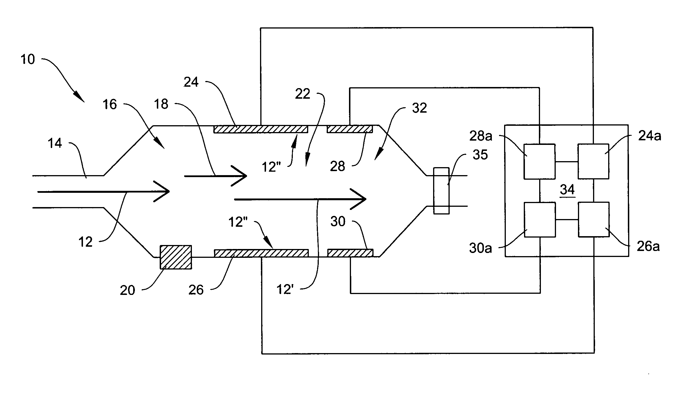
[0024] It is significant that the ion separator performs trajectory-based separation of ion species by applying a transverse separation field in the separator, and that detection of these separated species occurs within that same separator-detector space based upon the trajectory of the ion species in the field. No additional detector arrangement is required, and a compact and efficient chemical analyzer is provided. One advantage of this arrangement is that separation and detection can be obtained all within a single simple electrode bank structure. Multiple processing environments and data comparisons are not required. One other advantage is that using multiple electrodes in the electrode banks enables simultaneous detection of multiple ion species. This provides for a fast device with high throughput.
[0049] There are several modes of operation of the invention for sample characterization. As an illustration, for a given sample to be analyzed, one mode of operation may be adjusted to provide a first set of detection data for a first set of conditions while a second mode of operation may be adjusted to provide a second set of detection data for the same or for a second set of conditions. For example, high field trajectory-based detection might be used to detect isomers of a compound while the FAIMS mode might be used to detect monomers of a compound in a sample, or vice versa, according to the character of the target (suspected) analytes of interest. Combination of resulting detection data enables rapid characterization of the components in a chemical sample with a high degree of confidence.

Problems solved by technology

Furthermore, recent events have seen members of the general public exposed to dangerous chemical compounds in situations where previously no thought was given to such exposure.
However, mass spectrometers are quite expensive, easily exceeding a cost of $100,000 or more and are physically large enough to become difficult to deploy everywhere the public might be exposed to dangerous chemicals.
Mass spectrometers also suffer from other shortcomings such as the need to operate at relatively low pressures, resulting in complex support systems.
Accordingly, mass spectrometers are generally difficult to use outside of laboratories.
This can result in detection errors, sometimes referred to as “false positives”.

Method used


Image

  • System for trajectory-based ion species identification
  • System for trajectory-based ion species identification
  • System for trajectory-based ion species identification

Examples


Embodiment Construction

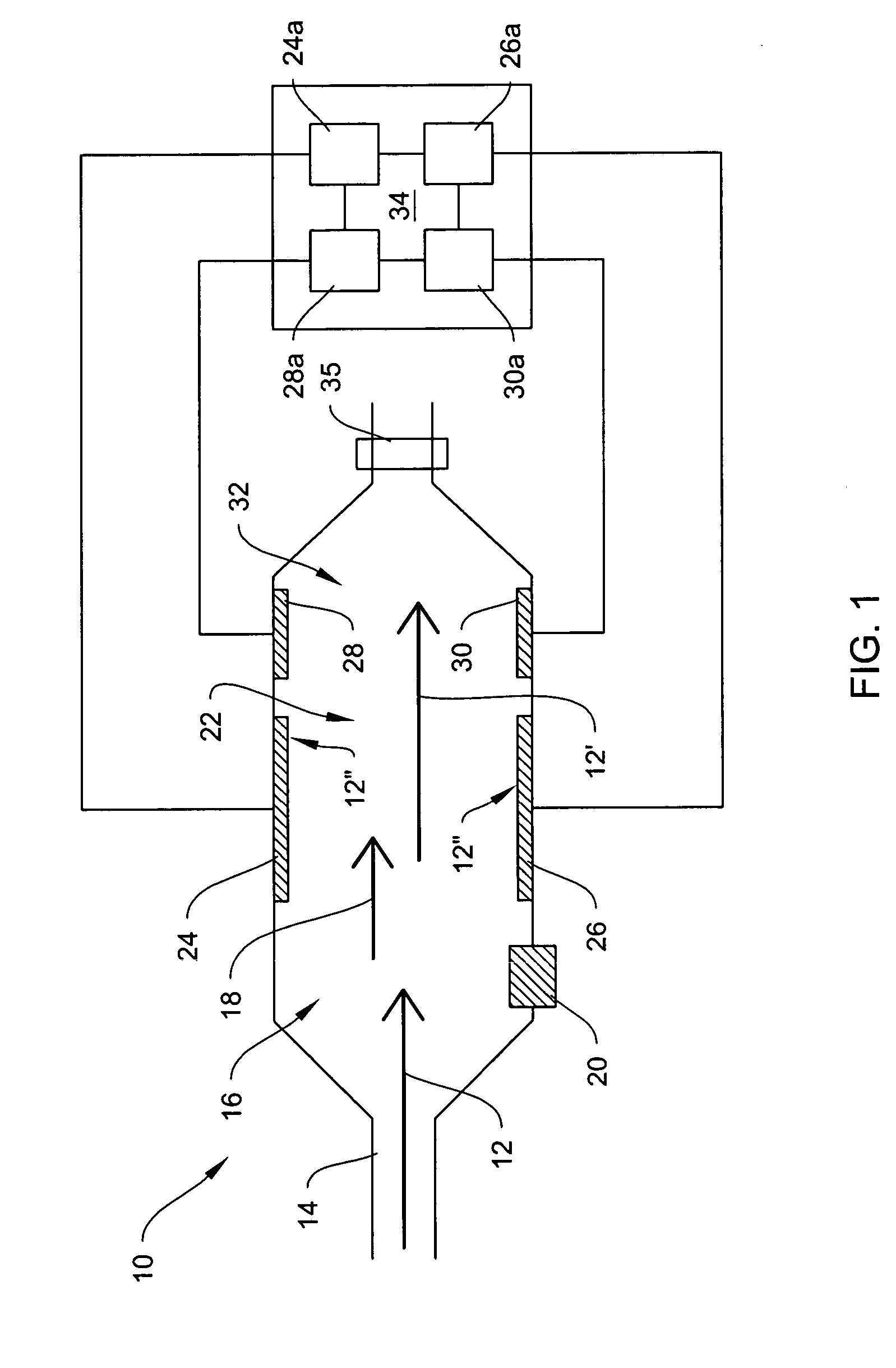
[0051] A FAIMS spectrometer 10, shown in FIG. 1, receives a chemical sample 12 at inlet 14. The sample flows into ionization region 16 in flow path 18, where it is ionized by ionization source 20. Ionization of the compounds in the sample creates ionized molecules (“ions”) that are carried by a transport or carrier medium into the ion filter 22 in flow path 18 between filter electrodes 24, 26. Embodiments of a compact and efficient high field asymmetric ion mobility spectrometer are disclosed in U.S. Pat. No. 6,495,823 (ion transport by carrier gas) and in U.S. Pat. No. 6,512,224 (electric field ion transport), incorporated herein by reference. Systems of the invention may include plate type or cylindrical type electrodes and the like.

[0052] A compensated, asymmetric high electric field is generated between the filter electrodes that has differential impact upon mobility of the ions according to their size, charge and cross-section, and mass. This mobility difference produces a cha...


PUM


Abstract

Method and apparatus for field ion mobility spectrometry for identification of chemical compounds in a sample by trajectory of sample ions in a transverse electric field.

Description

CROSS REFERENCE OF RELATED APPLICATIONS [0001] This application is a continuation-in-part of U.S. application Ser. No. 10 / 278,738, filed Oct. 22, 2002, which is a continuation-in-part of U.S. application Ser. No. 10 / 187,464, filed Jun. 28, 2002, which is a continuation-in-part of U.S. application Ser. No. 09 / 896,536, filed Jun. 30, 2001, and which claims the benefit of U.S. Provisional Application No. 60 / 340,894, filed Oct. 30, 2001, U.S. Provisional Application No. 60 / 334,685, filed Nov. 15, 2001, U.S. Provisional Application No. 60 / 351,043, filed Jan. 23, 2002, and also claims the benefit of U.S. Provisional Application No. 60 / 336,506, filed Oct. 23, 2001, and U.S. Provisional Application No. 60 / 336,522, filed Oct. 23, 2001. [0002] This application is a continuation-in-part of U.S. application Ser. No. 10 / 321,822, filed Dec. 16, 2002, which is a continuation of U.S. application Ser. No. 09 / 358,312, filed Jul. 21, 1999 (now issued U.S. Pat. No. 6,495,823, issued Dec. 17, 2002). [00...

Claims


Application Information

Patent Timeline
IPC IPC(8): G01N27/64H01J49/42
CPCG01N27/624
Inventor MILLER, RAANAN A.NAZAROV, ERKINJON G.KAUFMAN, LAWRENCE A.
Owner DH TECH DEVMENT PTE
Learn More