
System and method for rapid design, prototyping, and implementation of distributed scalable architecture for task control and automation

a task control and automation technology, applied in the field of data processing system for modeling and implementation of scalable distributed systems, can solve the problems of complex industrial applications such as manufacturing process control, multi-component devices, other systems or devices, and the process of design, prototyping and implementation of complex industrial applications is a complex and time-consuming task, and the entire system is often re-designed and re-designed for a great deal of time and resources. , to achieve the effect of rapid and inexpensive design and

Inactive Publication Date: 2005-02-03
ANANTH VISWANATH +1
View PDF1 Cites 79 Cited by
  • Summary
  • Abstract
  • Description
  • Claims
  • Application Information

AI Technical Summary

Benefits of technology

[0026] The present invention is directed to a system and method for simplifying and accelerating the process of prototyping, real-world simulation, and implementation of virtually any task performance system or device, thereby dramatically reducing the design-to-implementation cycle time and expense. The inventive system includes a development system that provides a user, with visual tools to interactively and dynamically partition a previously designed visual system model of the task performance system or device, and then interactively or automatically assign the partitions to corresponding selectable target components, to produce a prototyped system ready for conversion to executable form suitable for implementation. The inventive system and method can also be readily used to automatically generate any instruction sets (e.g. programs, drivers, or modules) that are necessary for implementing the prototyped task performance system in actual target components of one or more emulation and / or production target systems. A novel automatic executable program code generation process that can be advantageously utilized is also provided in accordance with the present invention.
[0028] Advantageously, the inventive processes performed by the system of the present invention, are applicable to any visual system model that may be created with any form of visual design and / or modeling tools. While the inventive system may be readily implemented in a stand-alone configuration independent of any other design or modeling tools or environments, as a matter of design choice, it may be utilized in conjunction with existing visual system design tools for rapid and inexpensive design, prototyping, re-design, scaling, modification, and / or testing of task performance systems. This approach is very attractive because the user is able utilize an available and familiar graphical user interface and controls of the initial design system and at the same time use all of the novel features and capabilities provided in accordance with the present invention.
[0029] The system of the present invention may include an optional data handling system located as a component of, or proximal to, the implementation target system for enabling real time transmission of date from the target system to a remote development or other user system. Furthermore, the development system of the present invention, may be provided with an interactive user interface, at its output (i.e. display) system with novel tools and functionality that enable the user to readily design an interactive reconfigurable visual instrument panel for monitoring and / or management one or more remote target systems or devices.
[0030] Due to the novel features of the present invention, the prototyped model (or even the visual design model) may be quickly and easily modified at any time, for example, to account for changes in design or engineering requirements, target system factors, or to take advantage of new technologies, and / or lower-cost target components, without requiring the user to extensively re-design the visual model, or to write any program code.

Problems solved by technology

Traditionally, the process of design, prototyping and implementation of complex industrial applications (such as manufacturing process control, multi-component devices and other systems or devices), has been an extremely difficult, costly and time consuming task.
Typically, this process involved a long iterative, and often empirical, process, of formulating the requirements of the desired system, conceptually planning the system, developing a prototype, writing programs or other code necessary for implementation, testing the implemented prototype and then repeating many of the steps, in most cases including the arduous and frustrating coding of new programs, even when minor changes to the prototype are necessary.
In cases of more serious issues, the entire system is often re-designed further consuming a great deal of time and resources.
This trial and error approach of system and device design has been a challenge for engineers and designers for years.
Nevertheless, even with the aid of currently available powerful software tools, prototyping of a complex system or apparatus which generally requires a distributed architecture for its various operational parameters (such as an industrial process control application), it is a difficult and time consuming process with at least the following steps that must be performed by the user as part of the design to implementation cycle:
Because the key actions for all of the above tasks must be performed manually by the user, even with the assistance of the most powerful currently available design tools, the design-to-implementation cycle in continuous product development industries (such as automotive and aerospace industries), remains undesirably long.
In addition, changes to the system architecture or to system components during the prototyping process must be manually propagated through the entire system, thus resulting in a further significant delay and expense.
Furthermore, the most frustrating and difficult tasks for the user of previously known system design software tools—the second and third steps shown above—are still an ever-present requirement.
Finally, the majority of existing design software tools are generally limited to utilization in the field of embedded system design and cannot be readily used in other forms of distributed task performance systems.

Method used


Image

  • System and method for rapid design, prototyping, and implementation of distributed scalable architecture for task control and automation
  • System and method for rapid design, prototyping, and implementation of distributed scalable architecture for task control and automation
  • System and method for rapid design, prototyping, and implementation of distributed scalable architecture for task control and automation

Examples


first embodiment

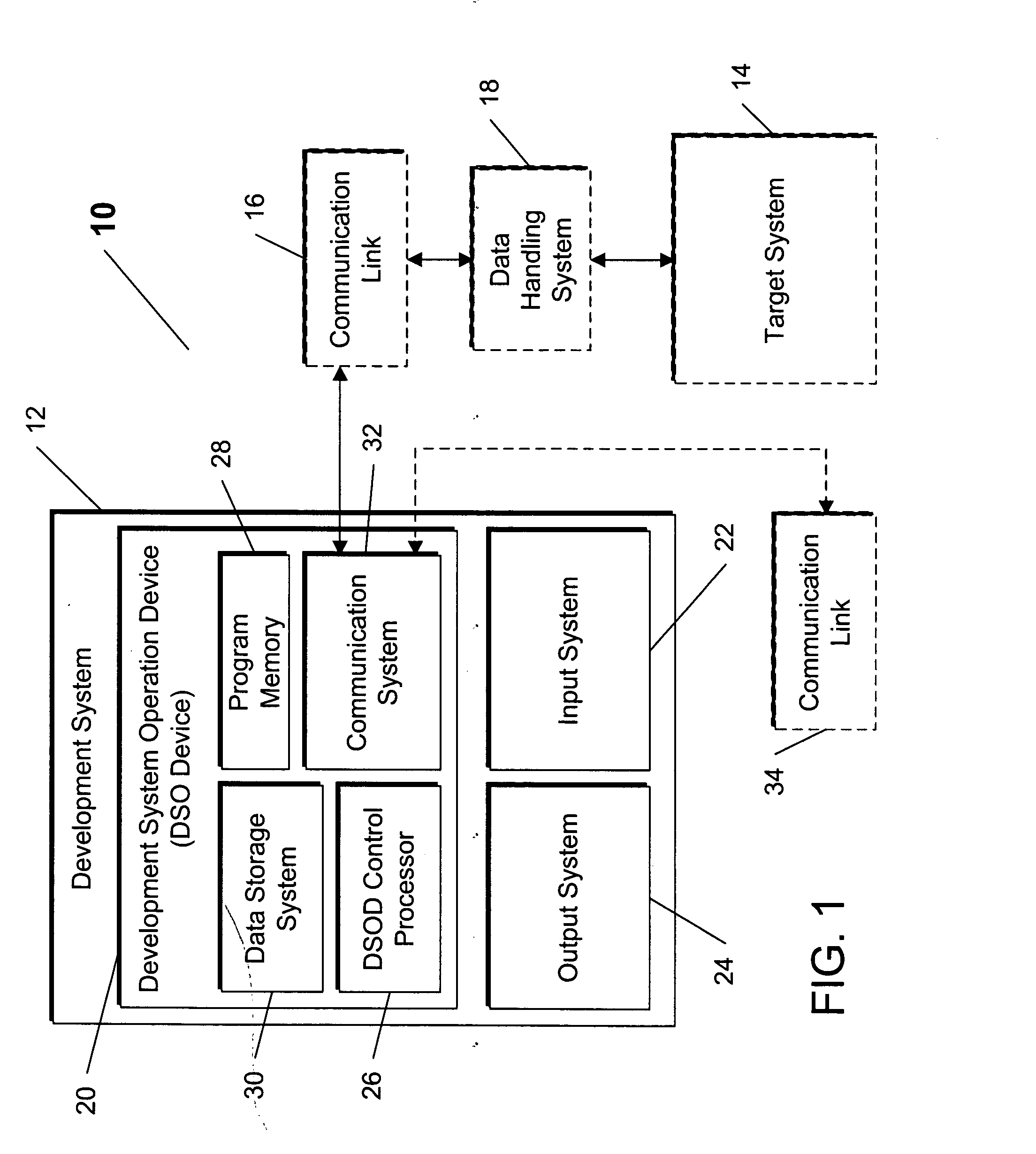
[0045] Referring now to FIG. 1, the inventive RDPI system 10 is shown. The key novel features of the RDPI system 10 are embodied in the inventive processes, described in greater detail below in connection with FIGS. 5-7 and 12, that may be implemented in whole or in part as one or more executable programs or other form of data processing tasks. These inventive processes enable the user to fully utilize the previously summarized novel and advantageous features of the RDPI system 10, as well as take advantage of numerous other novel features and options described below in connection with various figures.

[0046] The RDPI system 10 includes a development system 12 for enabling the user to quickly and easily create an operational system model (representative of a previously designed visual system model partitioned into individual model elements and / or model element groups (i.e., “partitions”) intended for assignment to particular target components, as well as the necessary communication l...

second embodiment

[0099] Referring now to FIG. 7, the primary partitioning process is shown as an automated process 400, The process 400 begins at a step 402, where the system 12 retrieves at least one previously developed implementation rule from a group of design rues, installation rules, business rules, that include specific predetermined parameters, ranges, or values of target component attributes, that correspond to attributes of desirable target components for use with the target system being developed. One or more of these rule sets may be previously configured for use with design of particular types or classes of target systems, and may also change over time as design requirements shift. Alternately, the rules may be implemented as expert systems.

[0100] At a step 404, the system 12 opens the target attribute records (such as the attribute record 100 of FIG. 4) for each possible target component, preferably opening the category(ies) of attributes matching the rule(s) opened at the step 204. At...


PUM


Abstract

The present invention provides a system and method for simplifying and accelerating the process of prototyping, real-world simulation, and implementation of virtually any task performance system or device, thereby dramatically reducing the design-to-implementation cycle time and expense. The inventive system includes a development system that provides a user, with visual tools to interactively and dynamically partition a previously designed visual system model of the task performance system or device, and then interactively or automatically assign the partitions to corresponding selectable target components, to produce a prototyped system ready for conversion to executable form suitable for implementation. The inventive system and method can also be readily used to automatically generate any instruction sets that are necessary for implementing the prototyped task performance system in actual target components of one or more emulation and / or production target systems. A novel automatic executable program code generation process that can be advantageously utilized is also provided in accordance with the present invention. Finally, the present invention may optionally include a data handling device that enables real-time monitoring and management of a remote target system from one or more user systems, as well as a set of tools for designing interactive visual instrument panels for that purpose.

Description

CROSS REFERENCE TO RELATED APPLICATIONS [0001] The present patent application claims priority from the commonly assigned U.S. provisional patent application Ser. No. 60 / 492,771 entitled “SYSTEM AND METHOD FOR RAPID DESIGN, PROTOTYPING AND IMPLEMENTATION OF DISTRIBUTED SCALABLE ARCHITECTURE FOR TASK CONTROL AND AUTOMATION” filed Aug. 2, 2003.FIELD OF THE INVENTION [0002] The present invention relates generally to a data processing system for modeling and implementation of scalable distributed systems that perform various tasks, and more particularly to a scalable architecture-based data processing system for simplified design, prototyping, and rapid implementation of task performance systems, including, but not limited to, industrial process control systems, other embedded systems, multi-component electrical, electronic, or electromechanical devices, and distributed computer systems. BACKGROUND OF THE INVENTION [0003] Traditionally, the process of design, prototyping and implementati...

Claims


Application Information

Patent Timeline
IPC IPC(8): G06F9/44G06F17/50G06Q10/00
CPCG05B2219/23261G06F8/20G06Q10/00G06F17/5009G06F17/50G06F30/00G06F30/20G06F9/44G06F2119/18
Inventor ANANTH, VISWANATHSURI, ANDY
Owner ANANTH VISWANATH
Learn More