Method and apparatus for improved ultraviolet (UV) treatment of large three-dimensional (3D) objects

a three-dimensional object and ultraviolet treatment technology, applied in the direction of optical radiation measurement, fluorescence/phosphorescence, instruments, etc., can solve the problems of limiting existing radiation sources, irregular finished products, and inability to cure clear coatings instantaneously by thermal treatment, so as to improve improve the control of irradiance and/or absorbed energy or light flux. , the effect of increasing the uniformity of radian

Inactive Publication Date: 2005-02-03
HERAEUS NOBLELIGHT AMERICA
View PDF12 Cites 18 Cited by
  • Summary
  • Abstract
  • Description
  • Claims
  • Application Information

AI Technical Summary

Benefits of technology

The invention eliminates the need for the superposition of more than one light source to provide a specific surface irradiance distribution required for a specific three-dimensional substrate to perform the above methods.
The invention eliminates the need for the prior art mechanical systems, which rotate, articulate or translate one or more light sources to average the surface irradiance distribution over a specific three-dimensional substrate.
The invention eliminates the need for the prior art mechanical systems which rotate, articulate or translate three-dimensional objects in the light beam of one or more one light sources to average the irradiance distribution over a specific three-dimensional substrate.
According to a second aspect of the invention, a least one transmissive or reflective holographic element modifies the output beam profile by introducing changes in the phase of more than one wavefront on a point-by-point basis along one or more parts of the wavefront. The phase changes are chosen to vary the shape of the wavefront so that the shape of the wavefront and the shape of the surface of the three-dimensional are substantially similar. This similarity makes the direction of the beam and the surface normal of the three-dimensional surface more coincident and increases the uniformity of the radiance of the output beam or light flux on a point-by-point basis over at least one surface of the three-dimensional object.
The modified output beam provides better control of the irradiance and / or absorbed energy or light flux during the treatment process.

Problems solved by technology

The curing of clear coatings by thermal treatment is not instantaneous and usually requires times ranging from minutes to hours.
Otherwise, irregularities in the finished product will result.
This limits existing radiation sources to the treatment of three-dimensional objects that are smaller than the depth-of-field when a uniform irradiation of product is required.
A drawback inherent in this approach is that multiple scattering increases the path length of a ray in the translucent material and its absorption.
Such systems may be inefficient given that energy is removed from the treatment beam.
The absorption of energy in the diffuser may lead to excessive heating of the optics and a need to provide active or passive cooling devices to prevent damage to the optics or any adjacent component of the treatment system.
Finally, energy absorption may damage the optical system in ways unrelated to purely thermal effects.
Modification of optical components to increase beam divergence or randomness can reduce the original performance of the optical component.
A significant limitation of this technique is the requirement that no part of the 3D object blocks the incident beam.
If this occurs, then parts of the 3D object will not receive the beneficial treatment provided by the radiant energy.
This approach to 3D curing increases the cost of the curing system by increasing the number of curing beam sources or the number of optical components like lenses, mirrors or optical fibers.
While an effective method for improved treatment of 3D objects, there is an increased cost for the mechanical components needed to move the treatment beam source.
A drawback in the holographic technique is the requirement to use a coherent radiation source or laser.
Lasers are very inefficient in the conversion of electrical energy into radiant energy and have a small aperture and narrow beam.
The latter limitation makes it hard to project a laser beam over a large solid angle.

Method used


Image

  • Method and apparatus for improved ultraviolet (UV) treatment of large three-dimensional (3D) objects
  • Method and apparatus for improved ultraviolet (UV) treatment of large three-dimensional (3D) objects
  • Method and apparatus for improved ultraviolet (UV) treatment of large three-dimensional (3D) objects

Examples


Embodiment Construction

In the following description of the present invention, reference is made to the accompanying drawings that form a part, hereof, and in which are shown by way of illustration the various embodiments in which the invention may be practiced. It is understood that other embodiments may be utilized, and that structural and functional modifications may be made without departing from the scope of the present invention.

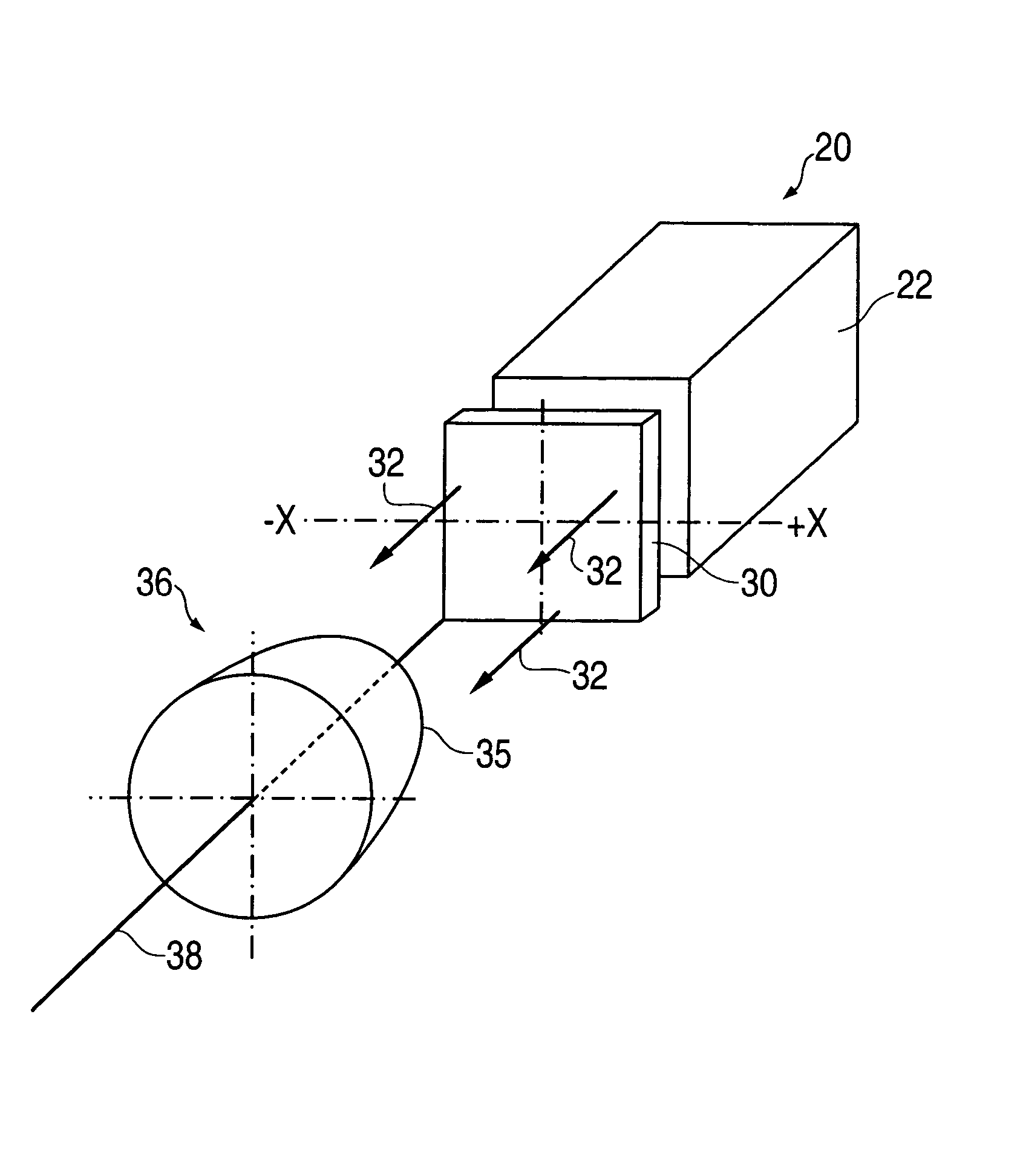
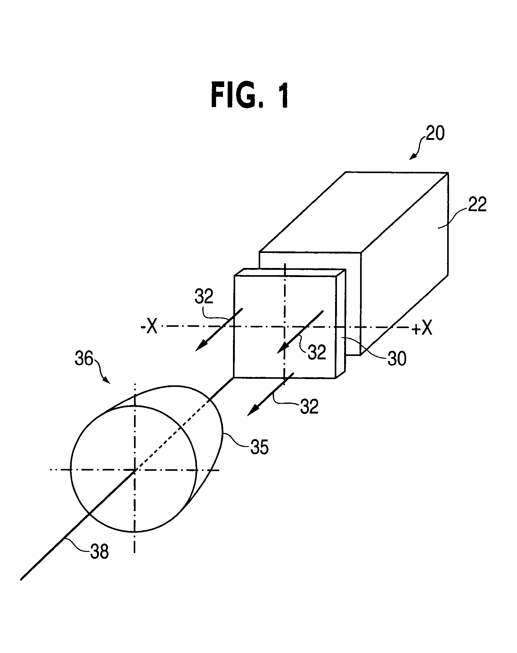
FIG. 1 depicts a first embodiment of an irradiation apparatus 20 in accordance with the present invention. The apparatus 20 includes a UV radiation source 22, which is depicted as a rectangular enclosure with a square aperture. The radiation source 22 is a light source such as a source of UV in the preferred embodiments of the invention, and for example may be a plasma discharge lamp (microwave electrodeless discharge lamp, an arc discharge lamp, a fluorescent discharge lamp) constructed or filtered to radiate predominantly in the desired wavelength ranges, such as, for UV,...


PUM


Abstract

The invention is a method of irradiating at least one surface of a three-dimensional object (36, 114) with a desired ultraviolet light irradiance flux produced by an ultraviolet light source (22, 102). The invention determines a position at which the three-dimensional object will be positioned relative to the ultraviolet light source when the at least one surface (35, 113) is to be irradiated with the desired ultraviolet light flux; determines an unmodified ultraviolet light flux which would irradiate the at least one surface when the ultraviolet light source is activated while the three-dimensional object is at the position relative to the ultraviolet light source; produces an optical element (30, 112), based upon the unmodified ultraviolet light flux and the desired ultraviolet light fluxes, which provides a modified wavefront of the ultraviolet light flux to irradiate the at least one surface with the desired ultraviolet light flux; positions the optical element in the path which the wavefront of the ultraviolet light from the ultraviolet light source would follow in irradiating the at least one surface; and activates the ultraviolet light source to image transmit the ultraviolet light flux from the ultraviolet light source on to the optical element to cause irradiation of the at least one surface with the desired light flux.

Description

BACKGROUND OF THE INVENTION 1. Field of the Invention The present invention pertains to a method providing substantially improved irradiation of large areas of three-dimensional (3D) objects. More particularly, the present invention pertains to a method of projecting a high level of light flux in a non-uniform pattern onto a three-dimensional target surface so as to more uniformly treat the surface. 2. Description of the Prior Art Various manufacturing processes include treating 3D surfaces by illuminating surfaces with radiant energy, for example, ultraviolet light or irradiation of surfaces by particle beams, for example, electron beams. The radiation treatment may be related to curing, polymerization, oxidation, purification, disinfections, or some other procedure. By way of example, the manufacture of wood components for furniture involves the application of a clear coating onto the surface of the component for the purpose of surface protection and improvement of the appeara...

Claims


Application Information

Patent Timeline
Patent Type & Authority Applications(United States)
IPC IPC(8): G02B27/09
CPCG02B27/0938
Inventor RUCKMAN, MARK W.CEKIC, MIODRAGOKAMITSU, JEFFERY K.NILSSON, HANS DANIEL
Owner HERAEUS NOBLELIGHT AMERICA
Why Eureka
Try Eureka