
Biomedical electrode with current spreading layer

a biomedical electrode and current spreading technology, applied in the field can solve the problems of reducing the effectiveness of radiological images taken through the multifunctional biomedical electrode, difficult design of multifunctional biomedical electrodes, etc., and achieves the effects of reducing or eliminating hot spots, improving patient comfort, and lack of pliability in the conductive undercoating

Inactive Publication Date: 2005-01-20
3M INNOVATIVE PROPERTIES CO
View PDF28 Cites 61 Cited by
  • Summary
  • Abstract
  • Description
  • Claims
  • Application Information

AI Technical Summary

Benefits of technology

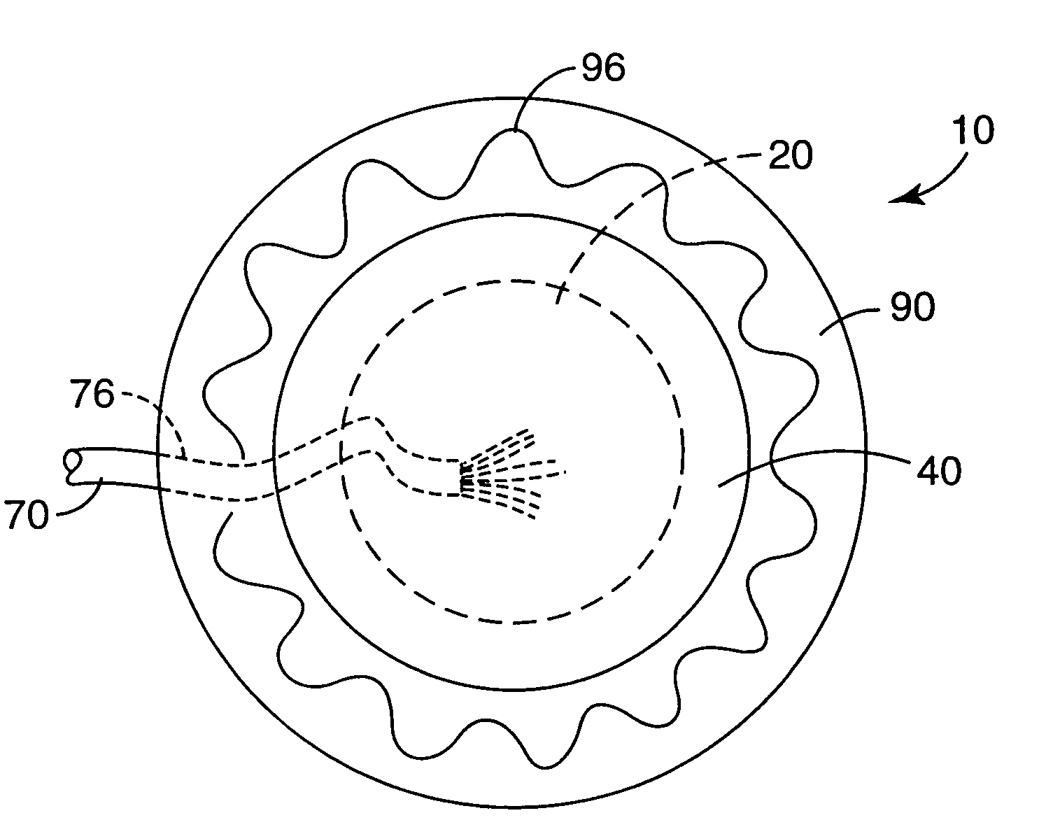
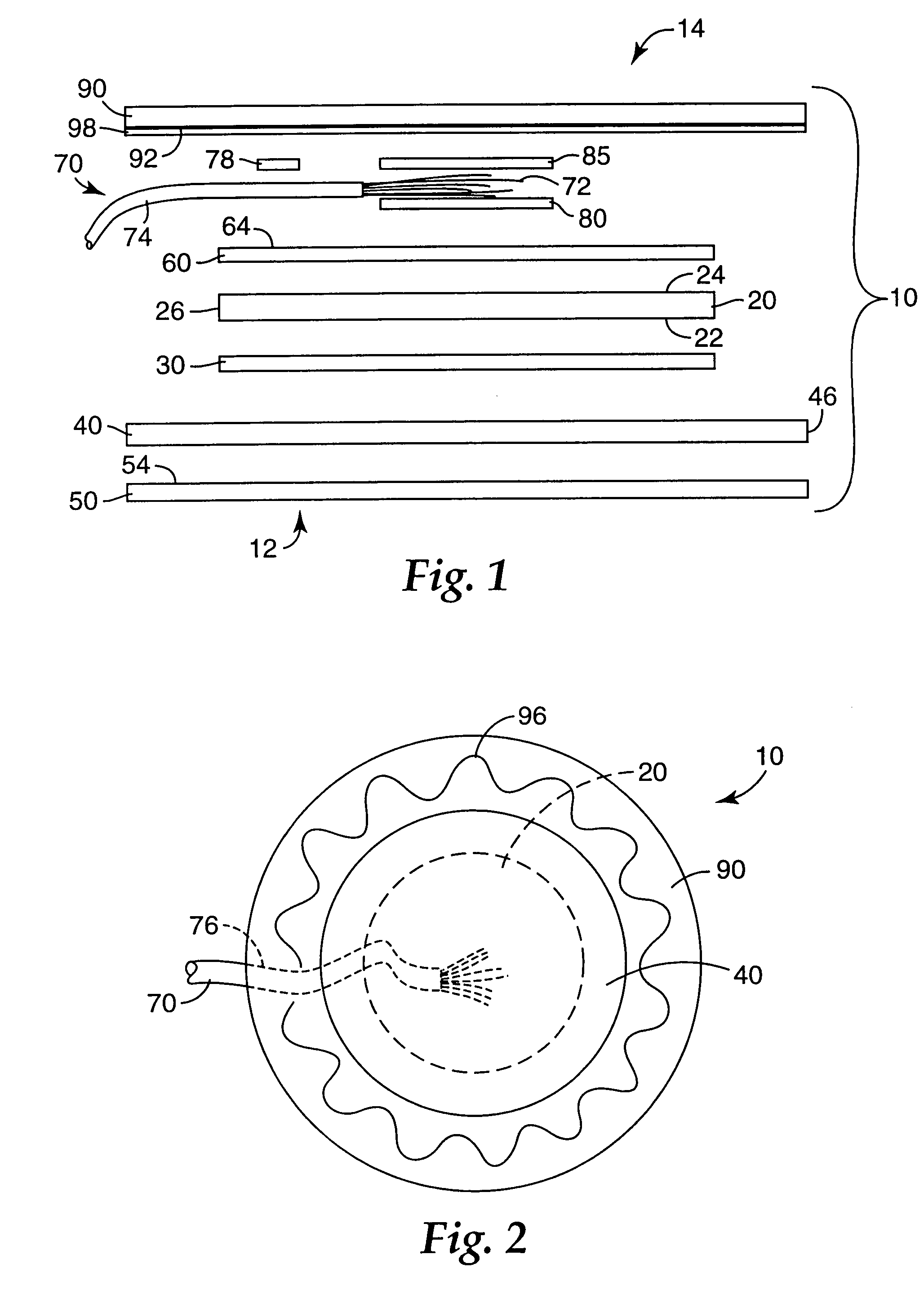
[0009] The distribution of electric current over substantially the entire surface of the conductive polymeric sheet by the current spreading layer may preferably reduce or eliminate the creation of hot spots directly underneath the connection between the electrical connector (e.g., lead) and the remainder of the electrode when used to deliver significant levels of electrical energy (e.g., defibrillation pulses). By reducing or eliminating hot spots, patient comfort may be improved during use of the multifunction biomedical electrodes of the present invention.
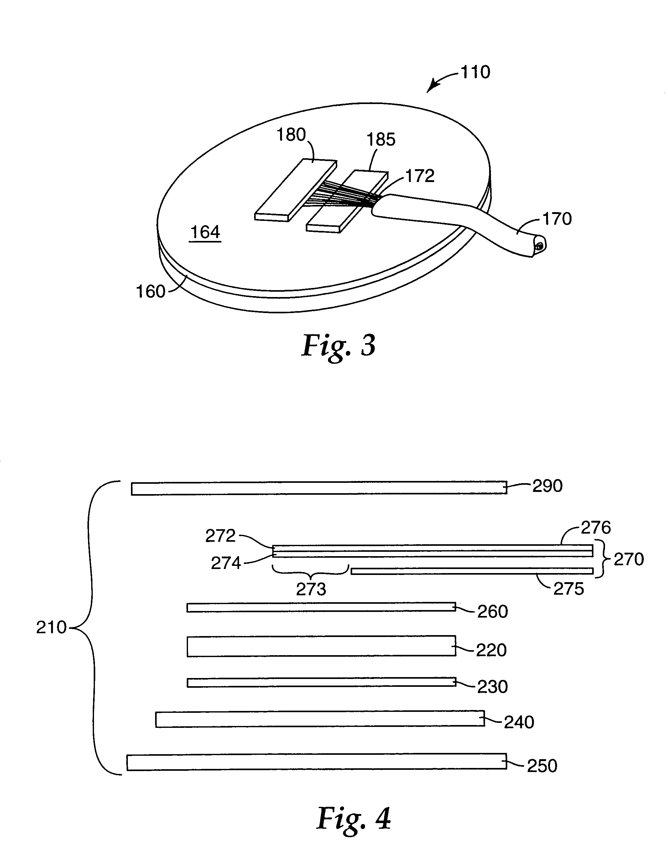
[0015] In addition, it may be preferred that the electrical connector be constructed of materials that also do not prevent effective radiological imaging. For example, the electrical connector may be provided in the form of a multi-stranded wire in which the strands are, for example, metal-coated carbon fibers or aluminum strands. In addition to using components for the conductive part of the wire that do not completely obscure radiological images, it may also be advantageous to provide the wire in a jacket that does not itself completely obscure radiological images.

Problems solved by technology

These requirements make the design of a multifunction biomedical electrode difficult, especially when, for example, the electrodes are required to provide cardiac pacing for extended periods of time (e.g., twelve hours or more).
One potential disadvantage of this approach is that the metal foil may reduce the effectiveness of radiological images taken through the multifunction biomedical electrode because of the shadow cast by the metal foil in any such radiological images.

Method used


Image

  • Biomedical electrode with current spreading layer
  • Biomedical electrode with current spreading layer
  • Biomedical electrode with current spreading layer

Examples


example 1

[0073] A conductive polymeric sheet with a thick silver ink layer coated on one side was obtained from Prime Label Inc. (Pewaukee, Wis.). The conductive polymeric sheet was made of PVC rendered electrically conductive by inclusion of carbon powder. The silver ink layer formed the current spreading layer of the electrode.

[0074] The opposite surface of the conductive polymeric sheet, i.e., the surface that was not coated with the silver ink forming the current spreading layer, was coated with an approximately 10 micrometer thick layer of silver-silver chloride ink (R301 available from Ercon Inc., Wareham, Mass.). The silver-silver chloride ink layer formed the conductive undercoating on the conductive polymeric sheet.

[0075] Pieces were cut out of the sheet with the current spreading layer and the conductive undercoating in rectangular shapes having sides with lengths of approximately 11 centimeters (cm) by 7 cm.

[0076] A hydrogel electrolyte adhesive with a thickness of 0.5 millimet...


PUM


Abstract

A biomedical electrode is disclosed that distributes current over the entire surface of a conductive polymeric sheet using a current spreading layer located on the upper surface of the conductive polymeric sheet (i.e., the surface facing away from the patient). The conductive polymeric sheet includes a conductive undercoating on its lower surface (i.e., the surface facing the patient). An electrolyte layer (e.g., a hydrogel pressure sensitive adhesive) is located on the bottom of the biomedical electrode, with the conductive undercoating located between the electrolyte layer and the conductive polymeric sheet. The biomedical electrode is in electrical communication with the patient's skin through the electrolyte layer.

Description

BACKGROUND [0001] Multifunction biomedical electrodes may be used for a variety of purposes. In some instances, multifunction biomedical electrodes may be used to defibrillate patients whose heart is in a state of fibrillation and in imminent danger of death. Multifunction biomedical electrodes may also be used for external pacing of the heart. Multifunction biomedical electrodes may also be required to function as ECG (electrocardiograph) monitoring electrodes when not providing defibrillation or pacing functions. [0002] These requirements make the design of a multifunction biomedical electrode difficult, especially when, for example, the electrodes are required to provide cardiac pacing for extended periods of time (e.g., twelve hours or more). Among the design constraints to be considered are that in, e.g., defibrillation, electrical energies of up to 360 Joules may be delivered repeatedly to a patient using the multifunction biomedical electrode. At such energy levels, currents ...

Claims


Application Information

Patent Timeline
Patent Type & Authority Applications(United States)
IPC IPC(8): A61B5/0408A61N1/04
CPCA61B5/0408A61N1/0408A61N1/0492A61N1/048A61N1/046A61B5/25A61B5/265A61B5/257A61B5/268A61B5/266
Inventor CARIM, HATIM M.
Owner 3M INNOVATIVE PROPERTIES CO
Learn More