
Double-gated transistor circuit

a transistor circuit and double-gate technology, applied in the field of digital gate logic circuitry, can solve the problems of large number of gates or gates in complex circuits, and achieve the effects of reducing size, reducing power dissipation, and high speed

Inactive Publication Date: 2005-01-06
AMERICAN SEMICON
View PDF22 Cites 24 Cited by
  • Summary
  • Abstract
  • Description
  • Claims
  • Application Information

AI Technical Summary

Benefits of technology

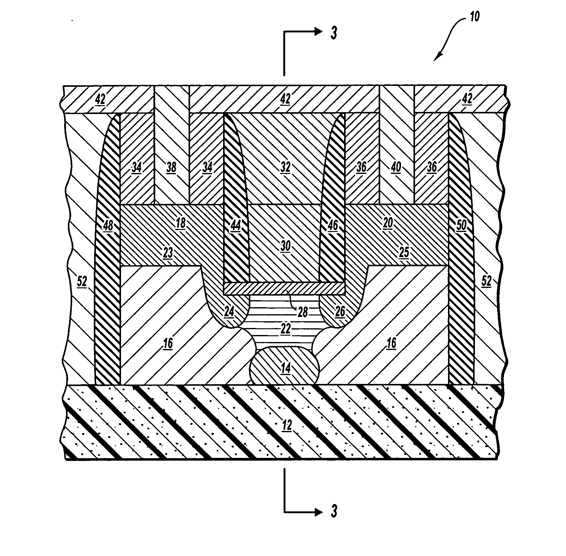
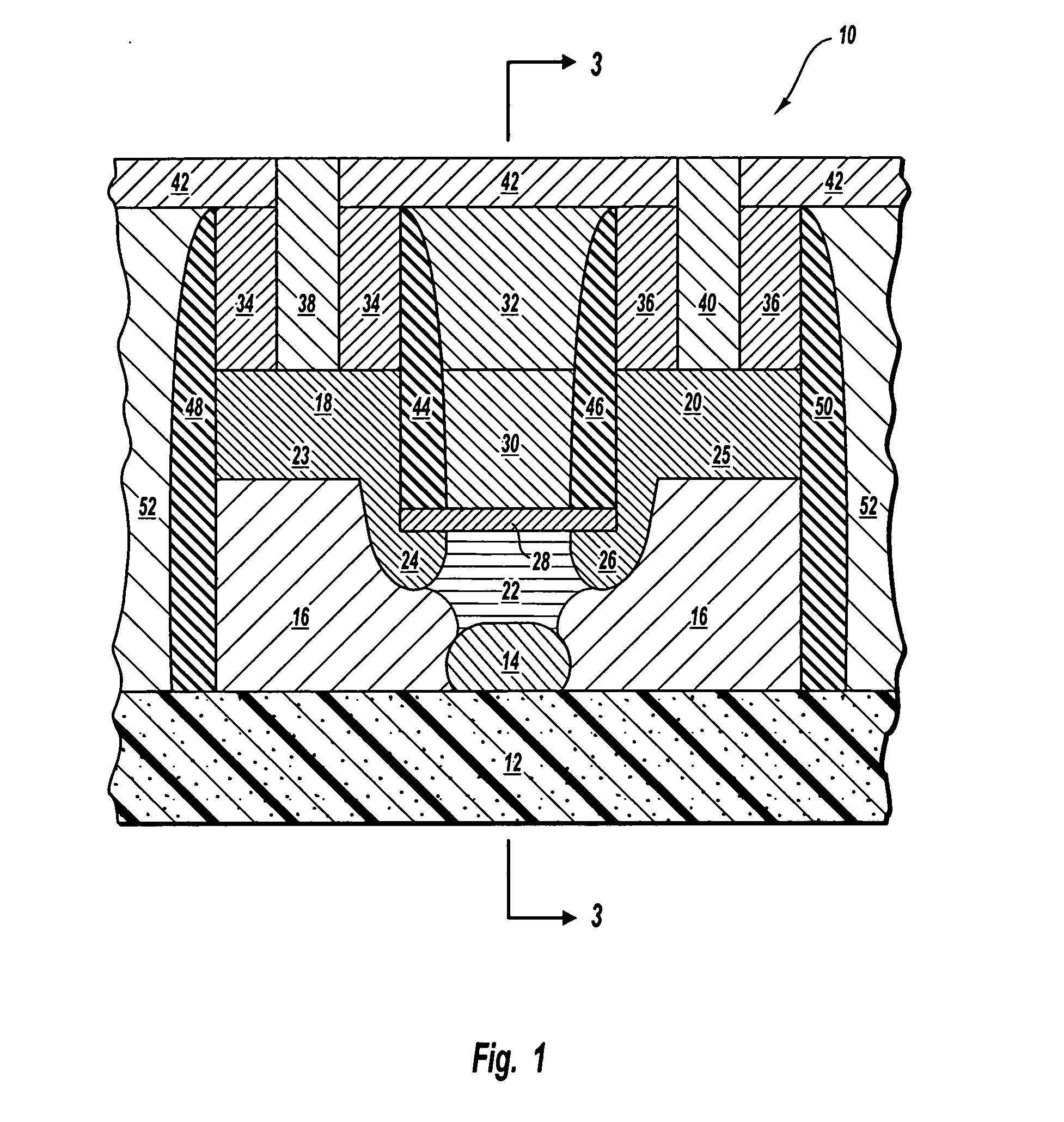
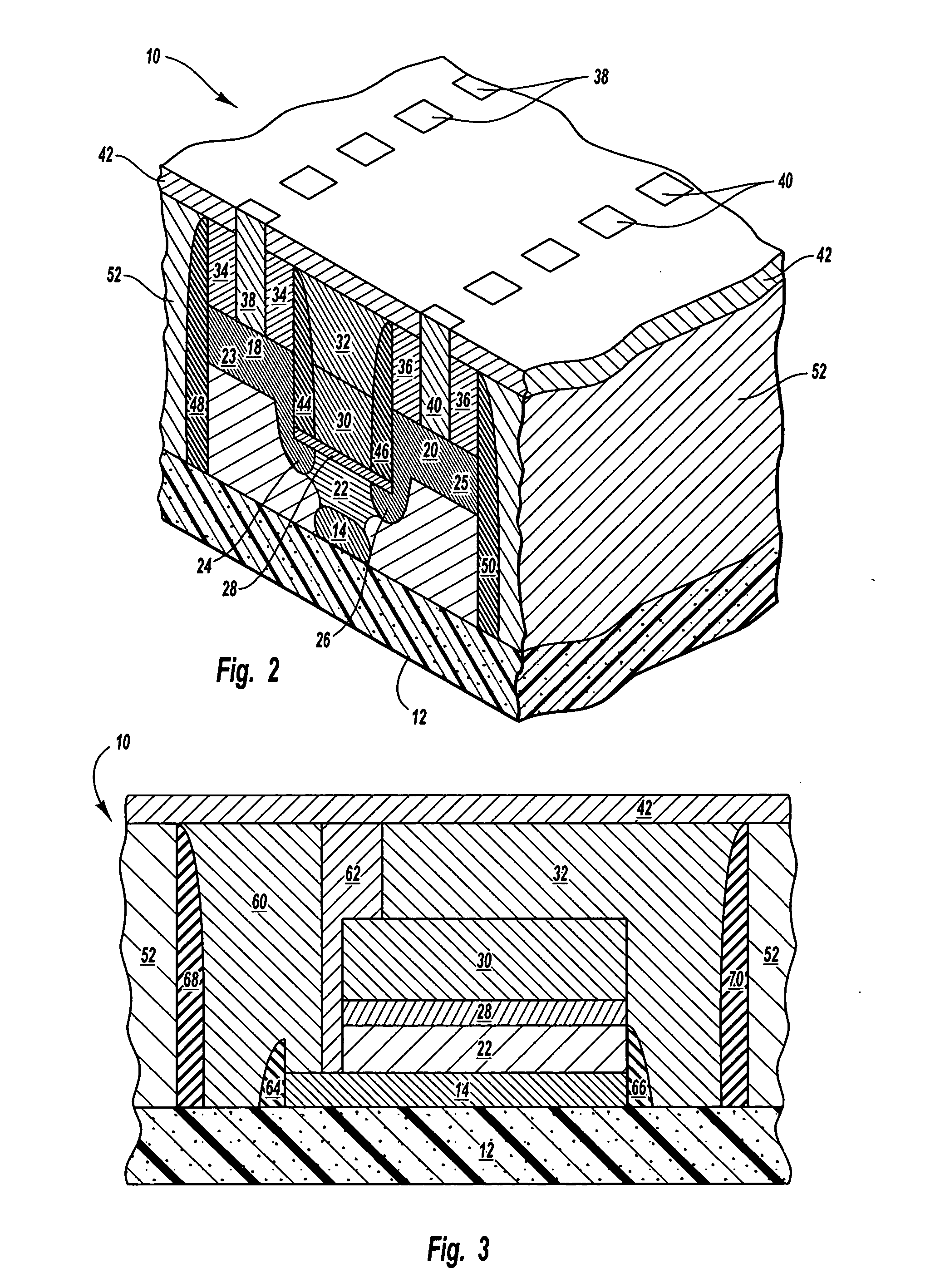
[0008] In one embodiment, the channel may have a U-shaped cross-sectional area to increase the channel length and gate control. A gate insulator is disposed on the channel with a top gate disposed on the channel. First and second insulating spacers are disposed on opposing sides of the top gate such that the first spacer is between the source and the top gate and the second spacer is between the drain and the top gate. The transistor may be surrounded with additional spacers and an isolation layer to provide full isolation.
[0009] The source includes a source extension that extends proximate to the first spacer and couples to the channel. Similarly, the drain includes a drain extension that extends proximate to the second spacer and couples to the channel. The spacers shield the channel from the field effect of the source and drain and further resist compression of the channel by the source and drain.
[0012] The single transistor OR gate reduces size, provides lower power dissipation, provides higher speed, and reduces instances of parasitic capacitance. Additional aspects and advantages of this invention will be apparent from the following detailed description of preferred embodiments, which proceeds with reference to the accompanying drawings.

Problems solved by technology

As can be expected, a vast number of OR gates are required in complex circuits.

Method used


Image

  • Double-gated transistor circuit
  • Double-gated transistor circuit
  • Double-gated transistor circuit

Examples


Embodiment Construction

[0038] Reference is now made to the figures in which like reference numerals refer to like elements. For clarity, the first digit or digits of a reference numeral indicates the figure number in which the corresponding element is first used.

[0039] Throughout the specification, reference to “one embodiment” or “an embodiment” means that a particular described feature, structure, or characteristic is included in at least one embodiment of the present invention. Thus, appearances of the phrases “in one embodiment” or “in an embodiment” in various places throughout this specification are not necessarily all referring to the same embodiment.

[0040] Furthermore, the described features, structures, or characteristics may be combined in any suitable manner in one or more embodiments. Those skilled in the art will recognize that the invention can be practiced without one or more of the specific details, or with other methods, components, materials, etc. In other instances, well-known structu...


PUM


Abstract

An OR gate circuit includes double-gated four terminal transistor with independent gate control. First and second inputs are independently coupled to the top and bottom gates of the transistor. The drain is coupled to an output and precharged to a low voltage. An input to either the top or bottom gates results in a high voltage to the drain and an output value of 1.

Description

RELATED APPLICATIONS [0001] This utility application claims priority to U.S. patent application Ser. No. 10 / 613,169 filed Jul. 3, 2003 and entitled Multi-Configurable Independently Double-Gated MOSFET and is hereby incorporated by reference.TECHNICAL FIELD [0002] The present invention relates to the digital gate logic circuitry and, more specifically, to an inclusive OR gate. BACKGROUND OF THE INVENTION [0003] In the dynamic industry of circuit design, the goal is always to develop components that are smaller and more efficient. The basic module of all digital circuits is the gate. Unlike analog circuits, digital circuits can have a few discrete input states. A gate is a simple digital circuit that produces a specific, predictable output condition for each possible input condition. When a gate is combined with other gates, they are able to perform complex logical and arithmetic operations. Gates are the physical realization of simple Boolean expressions. A gate's operation may be de...

Claims


Application Information

Patent Timeline
Patent Type & Authority Applications(United States)
IPC IPC(8): H01L21/225H01L21/336H01L21/8234H01L21/84H01L27/088H01L27/12H01L29/786H03K19/0948
CPCH01L21/2256H01L21/823437H01L21/84H01L27/088H01L27/1203H03K19/0948H01L29/66583H01L29/66772H01L29/7832H01L29/78648H01L29/66553
Inventor HACKLER, DOUGLAS R. SR.PARKE, STEPHEN A.
Owner AMERICAN SEMICON
Learn More