Image projecting device and method

Inactive Publication Date: 2004-12-02
EXPLAY
View PDF11 Cites 81 Cited by
  • Summary
  • Abstract
  • Description
  • Claims
  • Application Information

AI Technical Summary

Benefits of technology

[0015] The device of the present invention is lightweight and highly efficient, and is capable of utilizing a high-ratio polarized light source, high-efficiency SLM performing digital processing of data to be imaged so as to significantly reduce the speckles' associated effects, as well as performing digital processing of a projected image to improve its uniformity.
[0019] Preferably, if the use of polarized light is required, the light source used in the device of the present invention is of the kind generating a high-ratio polarized light beam (thereby eliminating the use of a polarizer at the input side of the SLM unit), and preferably also of the kind generating the light beam of the cross section substantially of the size of the active surface of the SLM unit (thus enabling the elimination of the beam shaping optics) or alternatively equipped with a beam shaping optics to provide the desired beam cross section.
[0024] Preferably, the device of the present invention comprises an image processor system (control unit) operable to carry out at least one of the following: applying digital processing to data indicative of an image to be projected so as to avoid or at least significantly reduce the speckle-associated effects in the projected image; processing of data indicative of the projected image to correct for non-uniformities in the light intensity; and analyzing data indicative of the environmental condition to adjust the intensity and / or the color mixture of the incident light beam.
[0027] The device of the present invention can be used with any conventional video generating device to project images onto an external screen surface. The device can be operable to project the same image with two different angles of projection, thereby enabling observation of the same image by two different observers, and also allows for private operation of the respective one of the images by each of the observers through his viewing area.
[0028] The technique of the present invention allows for combining images projected by several micro-projectors of the present invention, thereby allowing the creation of a large combined image; projecting the image onto a concaved screen surface; and creation of stereoscopic images by using two micro-projectors or the single micro-projector equipped with a rotating mirror.

Problems solved by technology

Common optical difficulties in the design of known projectors based on microdisplay are: low energy efficiency; low brightness and non-uniformity of the output image due to the source non-uniform intensity distribution (i.e. Gaussian distribution over the SLM surface) and intensity losses; low focus depth of the output image.
In laser based projectors, the "speckle" phenomena of a Laser source according to which, a granular pattern of light pervade the image, is also a technical difficulty.
Other common difficulties directly related to the optical difficulties and to the hardware implementation are: size, weight, optical complexity, power consumption and the mobility of the overall projecting device.

Method used


Image

  • Image projecting device and method
  • Image projecting device and method
  • Image projecting device and method

Examples


Embodiment Construction

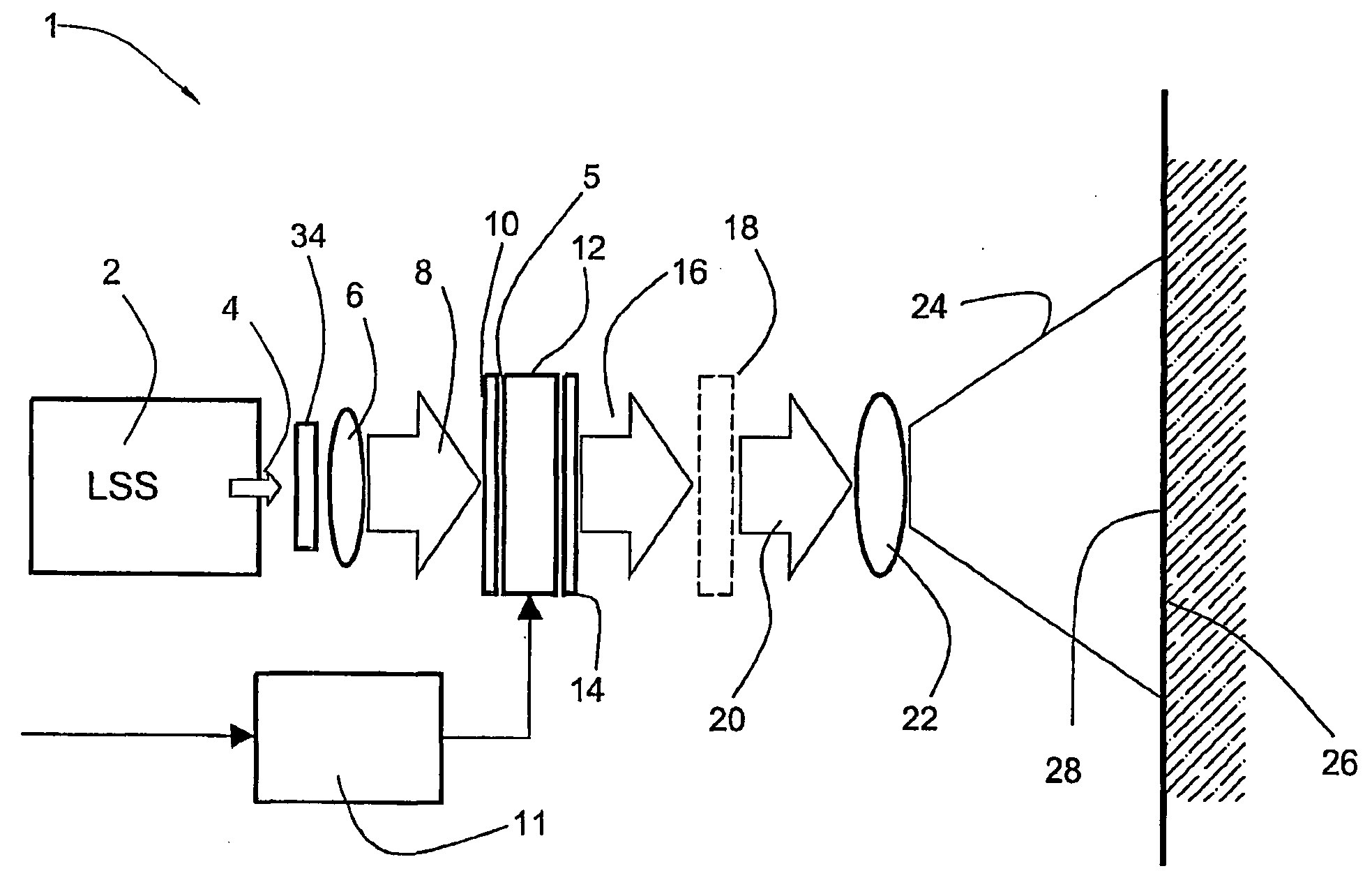
[0047] FIG. 1 is a schematic block diagram of a projecting device 1 according to the invention showing the optical components of a light propagation scheme. The device 1 comprises a light source system LSS including a light source 2 generating a collimated light beam 4, an optical arrangement including a diffractive element 34 ("top-hat") operable to affect the intensity distribution of the beam 4 to produce substantially uniform intensity distribution of the beam 4 within its cross section, and a beam shaping optics (beam expander) 6 that affects the cross section of the beam 4 to be substantially equal to the size of an active surface defined by a pixel arrangement 5 (the so-called "windowed structure") of an SLM unit 12 (such as the liquid crystal based SLM Module RS170 commercially available from Kopin Corporation, USA).

[0048] It should be noted that the provision of the beam expander 6 is optional, and the same effect can be achieved by providing an appropriate light source, fo...


PUM


Abstract

An image projecting device and method are presented. The device comprises a light source system operable to produce a light beam to impinge onto an active surface of a spatial light modulator (SLM) unit formed by an SLM pixel arrangement; and a magnification optics accommodated at the output side of the SLM unit. The light beam impinging onto the SLM pixel arrangement has a predetermined cross section corresponding to the size of said active surface. The SLM unit comprises first and second lens' arrays at opposite sides of the pixel arrangement, such that each lens in the first array and a respective opposite lens in the second array are associated with a corresponding one of the SLM pixels

Description

FIELD OF THE INVENTION[0001] This invention relates to a compact-size image projecting device and method.BACKGROUND OF THE INVENTION[0002] Microdisplays are miniaturized displays, typically with a screen size of less than 1.5" diagonal. Microdisplays are commonly used in data projectors, head mounted displays, and in the traditional viewfinders of digital cameras. Microdisplays can be implemented within compact projectors, in viewfinders of handheld Internet appliances and in mobile phones for Web surfing and videoconferences, because full computer screens can be viewed.[0003] Most microdisplays use a light-valve made of a silicon chip as the substrate material. The chip also houses the addressing electronics (at least an active matrix with integrated drivers), usually implemented in standard CMOS technology which allows very reliable and stable circuits, as well as very small pixel pitches (down to 10 .mu.m or even somewhat smaller), as well as high display resolutions.[0004] There...

Claims


Application Information

Patent Timeline
IPC IPC(8): G03B21/00G02B27/02G03B21/14H04N5/74H04N9/31
CPCH04N5/7416H04N9/315H04N9/3129H04N9/31
Inventor KAPELLNER, YUVALKAPELLNER, SHARONPOMERANTZ, ITZHAKZALEVSKY, ZEEVSABO, ERAN
Owner EXPLAY
Why Eureka
Try Eureka