
Software design system and method

a software design and software technology, applied in the direction of hardware monitoring, specific program execution arrangements, program control, etc., can solve the problems of affecting the development of performance prototypes, and affecting the development of software development systems

Inactive Publication Date: 2004-11-25
AUCKLAND UNISERVICES LTD
View PDF5 Cites 48 Cited by
  • Summary
  • Abstract
  • Description
  • Claims
  • Application Information

AI Technical Summary

Problems solved by technology

However, it is very difficult for system architects to determine appropriate architecture organisation, middleware and data management choices that will meet these requirements during architecture design.
Simulation tends to be rather inaccurate, performance prototypes require considerable effort to build and evolve, and existing system performance monitoring requires close similarity and often considerable modification to gain useful results.
However, many of these existing tools are not architecture focused and provide very uninformative modelling facilities that do not help a software engineer or architecture to make reliable decisions.
Two drawbacks of the SoftArch / MTE design tool are that the tool has a poor graphical user interface and that it is not based on UML.

Method used


Image

  • Software design system and method
  • Software design system and method
  • Software design system and method

Examples


Embodiment Construction

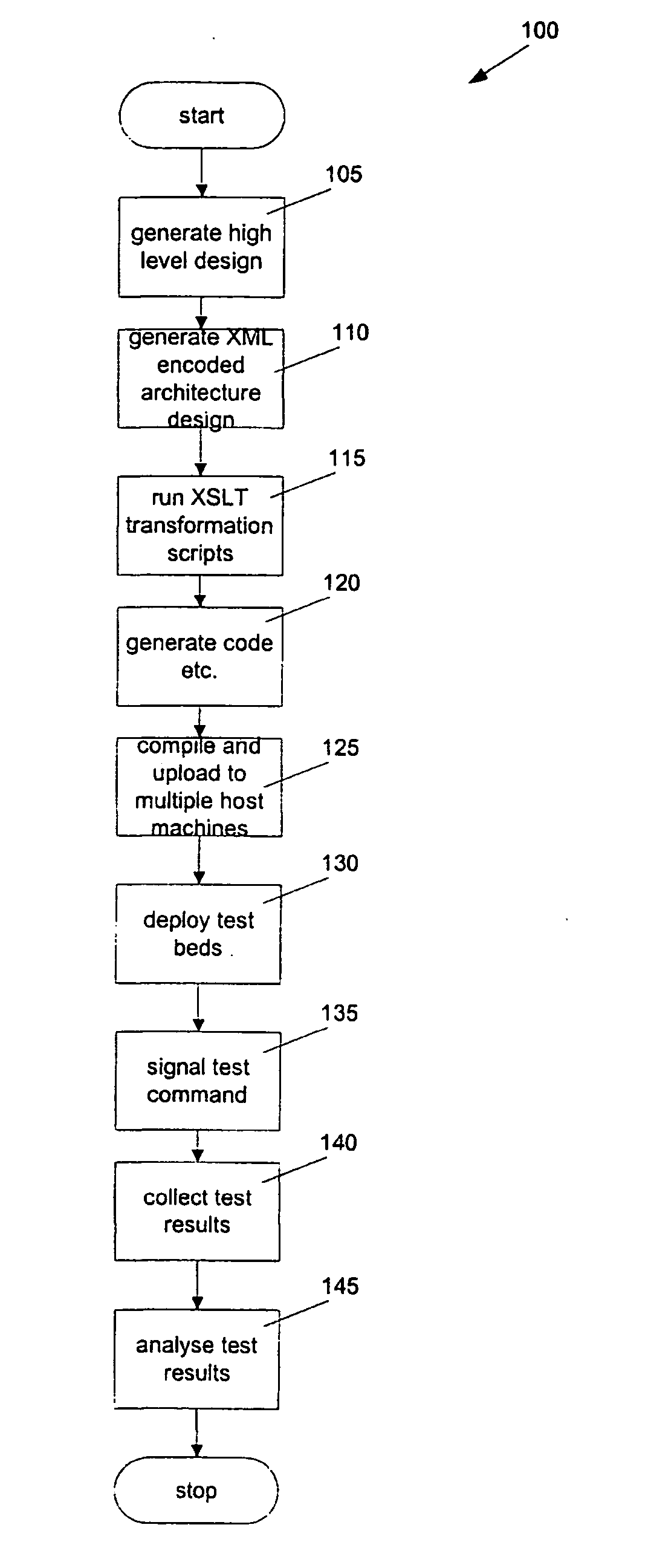
[0043] FIG. 1 illustrates a preferred form method 100 of generating a distributed system test bed in accordance with the invention. The first step is to generate 105 a high level design of a distributed system test bed. The preferred form generation involves a two step process in which a software architect defines a meta-model of the test bed initially and then defines one or more architecture models or modelling elements that are compatible with the meta-model. Each architecture model design is associated with an architecture meta-model and each architecture design may have one or more architecture models based on that meta-model.

[0044] The invention provides a software tool to enable a user to create a new meta-model or to load an existing meta-model from computer memory before going to architecture design. The process of generating high level design is further described below.

[0045] Using the high level design generated at step 105 above, the invention generates 110 an XML-encode...


PUM


Abstract

A method of generating a high level design of a distributed system test bed comprising the steps of defining a meta-model of the test bed; defining at least two architecture modelling elements within the meta-model to form an architecture model associated with the meta-model; defining at least one relationship between a pair of architecture modelling elements; defining properties associated with at least one of the architecture modeling elements; and storing the high level design in computer memory.

Description

[0001] The invention relates to a software design system and method. More particularly the invention relates to a software design tool for providing encoding of detailed software architecture information for generation of performance test beds.BACKGROUND TO INVENTION[0002] Most system development now requires the use of complex distributed system architectures and middleware. Architectures may use simple 2-tier clients and a centralised database, may use 3-tier clients, an application server and a database, may use multi-tier clients involving decentralised web, application and database server layers and may use peer-to-peer communications. Middleware may include socket (text and binary protocols); Remote Procedure (RPC) and Remote Method Invocation (RMI), DCOM and CORBA, HTTP and WAP, and XML-encoded data.[0003] Data management may include relational or object-oriented databases, persistent objects, XML storage and files. Integrated solutions combining several of these approaches, ...

Claims


Application Information

Patent Timeline
Patent Type & Authority Applications(United States)
IPC IPC(8): G06F9/44G06F11/34G06F11/36
CPCG06F8/20G06F11/3466G06F11/3664G06F11/3684
Inventor GRUNDY, JOHNHOSKING, JOHN GORDONCAI, YUHONG
Owner AUCKLAND UNISERVICES LTD
Learn More