Multiple power converter system using combining transformers

a transformer and power converter technology, applied in the direction of power conversion systems, dc-dc conversion, instruments, etc., can solve the problems of reducing the operating voltage of microprocessors, limiting the removal of heat, and affecting the efficiency of power conversion, etc., to achieve high efficiency, reduce costs, and fast response

Inactive Publication Date: 2004-11-25
INTEGRATED DEVICE TECH INC
View PDF57 Cites 27 Cited by
  • Summary
  • Abstract
  • Description
  • Claims
  • Application Information

AI Technical Summary

Benefits of technology

[0029] It is another object of the present invention to maintain that efficiency over a wide range of load conditions.
[0030] It is yet another object of the invention to provide a source of low voltage dc power at high currents which can sustain its voltage across a varying load even in the presence of high rates of change of current draw.
[0031] It is also an object of the preset invention to provide closer control of the output voltage of the power converter, even for extremely short time periods. That is to say, it is an object to provide a power source with better transient response to changes in load.
[0033] It is additionally an object of the present invention to provide a power conversion system which can be produced at lower cost than alternative approaches with similar characteristics.
[0034] Accordingly, the present invention is directed to a system of power conversion for performing a conversion from medium voltage dc to low voltage, high current dc at the point of power consumption with high efficiency and fast response.

Problems solved by technology

As the chip designers push to higher and higher speeds, problems may arise which relate to thermal issues.
There may be a tendency, therefore, to lower the operating voltage of microprocessors.
potential limitations to the removal of heat;
Therefore, designers may be driven to increase the speed, potentially driving the size of the chips smaller, the voltages lower, and the power up.
This may mean that the current rises very rapidly.
A processor may be drawing very little current because it is idling, and then an event may occur (such as the arrival of a piece of key data from a memory element or a signal from an outside event) which may cause the processor to suddenly start rapid computation.
This may produce an abrupt change in the current drawn by the processor, which may potentially have serious electrical consequences.
It may also require an unusually low output impedance or inductance.
The energy stored in the system may be supplied by the source of electrical current, and for a given power source there may be a limit to the rate at which energy can be supplied, which means that the stored energy must be built up over time.
Therefore, the presence of an energy storage mechanism may slow down a circuit, as the energy may be produced and metered into the magnetic field at some rate before the current can build up.
While it may be suggested that capacitors might be used to supply energy during the delay interval required for the current in the conductors to rise, the inductance of the connections to the capacitors may be considered limiting to this approach.
This requirement may become increasingly prevalent as the voltages drop and the currents increase, because the former may reduce the allowable transient size and the latter may increase the potential rate of change of current.
Both factors may reduce the permissible inductance of the connection.
While it may possible to create a low voltage regulated dc power source using simple transformers, rectifiers, and linear regulators, such units may generally be heavy, bulky and inefficient.
In these applications it may be desirable to reduce weight and size, and these approaches may be unsuitable for this reason alone.
In addition, the inefficiency of linear regulators may also be unacceptable.
Efficiency may be defined as the ratio of output power to input power, and a low efficiency might imply that heat is being developed in the unit which could be transferred to the environment to keep the unit cool.
There may be several other problems with this standard approach, and one of particular relevance here may relate to the speed of response of the regulation system.
A rapid change in the load impedance may cause a disturbance in the output voltage unless corrected, possibly by some control loop.
This disturbance may be caused by the response of the filtering system used to remove the alternating component from the square wave output.
Storing less energy may require reducing the value of the inductance and capacitance, but may be limited in the ability to reduce these values by the potential necessity to adequately remove the ac component (called "ripple") generally at the output of the filter.
The ripple may be reduced for a given value of inductance and capacitance by increasing the switching frequency, but this again may be limited by the ability of the electronic switches used in creating the square waveform from the dc input.
Such switches may have a limited operating frequency, and may exhibit losses (known as "switching losses") which may increase with the operating frequency.
Accordingly, substantial attempts such as those previously described by those skilled in the art may not have fully addressed the considerations raised.

Method used


Image

  • Multiple power converter system using combining transformers
  • Multiple power converter system using combining transformers
  • Multiple power converter system using combining transformers

Examples


Embodiment Construction

[0055] As can be easily understood, the basic concepts of the present invention may be embodied in a variety of ways. These concepts involve both processes or methods as well as devices to accomplish such. In addition, while some specific circuitry is disclosed, it should be understood that these not only accomplish certain methods but also can be varied in a number of ways. As can be seen from the drawings, the basic concepts of the present invention may be embodied in many different ways. Importantly, as to all of the foregoing, all of these facets should be understood to be encompassed by this disclosure.

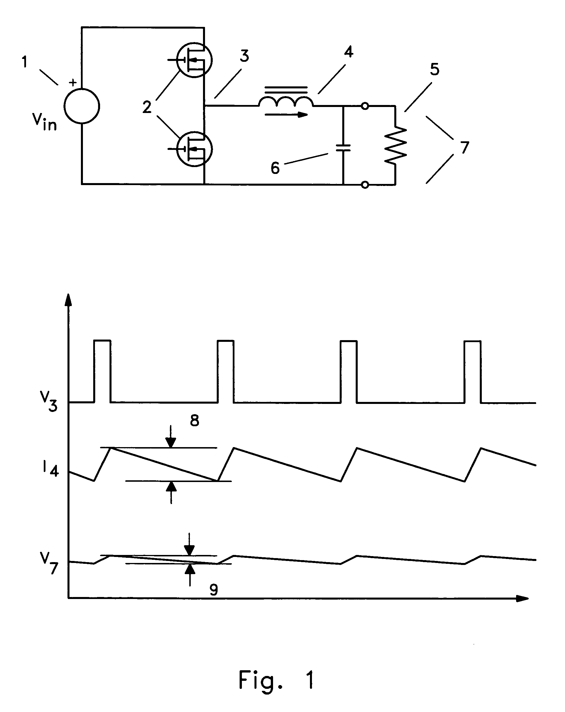
[0056] In the production of a low regulated dc voltage from a higher voltage source, the so-called "buck" converter may be commonly used. This converter, illustrated in FIG. 1, may be considered a simple circuit with generally four basic components: two electronic switches, one inductor, and one capacitor. If the output voltage is large compared with the voltage drop across a dio...


PUM


Abstract

Methods and circuitry for combining the outputs of multiphase power converters which greatly improves the transient response of the power conversion system are presented in a variety of embodiments. Transformers (e.g., 59, 60, 61, 62) may be used to accomplish the combining function, and with properly phased and connected windings it is possible to achieve a great reduction in output ripple current and a simultaneous reduction in transistor ripple current, which give the designer freedom to reduce the value of the system output inductor (e.g., 68), improving transient response.

Description

I. TECHNICAL FIELD[0001] The present invention generally relates to the area of powering low voltage, high current electronics such as found in the field of computing, and much of the following description is presented in that context. The invention is applicable to a wide variety of circumstances wherein a variety of power absorbing loads may abruptly change their power absorbing characteristics (that is to say, their impedance may undergo a rapid change). The invention may also be applicable if such loads are separated physically such that the voltage which may be dropped across the dynamic impedance of the power carrying conductors is a significant fraction of the voltage delivered to such loads. It may also be increasingly applicable to applications wherein design tradeoffs are forcing a steady decrease in operating voltages. Such situations may arise in telecommunications, radar systems, vehicle power systems and the like, as well as in computing systems.II. BACKGROUND[0002] Th...

Claims


Application Information

Patent Timeline
IPC IPC(8): H02M3/158H02M3/28
CPCH02M3/1584H02M3/285H02M2001/0074H02M1/0074
Inventor LEDENEV, ANATOLI V.PORTER, ROBERT M.GUROV, GENNADY G.
Owner INTEGRATED DEVICE TECH INC
Why Eureka
Try Eureka