
Magnetic transfer holder and magnetic transfer device

a magnetic transfer and magnetic technology, applied in the field of magnetic transfer holders and magnetic transfer devices, can solve the problems of insufficient tracking function, signal quality level deterioration, and uniform contact between slave medium and master information carriers

Inactive Publication Date: 2004-09-30
FUJIFILM CORP +1
View PDF5 Cites 3 Cited by
  • Summary
  • Abstract
  • Description
  • Claims
  • Application Information

AI Technical Summary

Benefits of technology

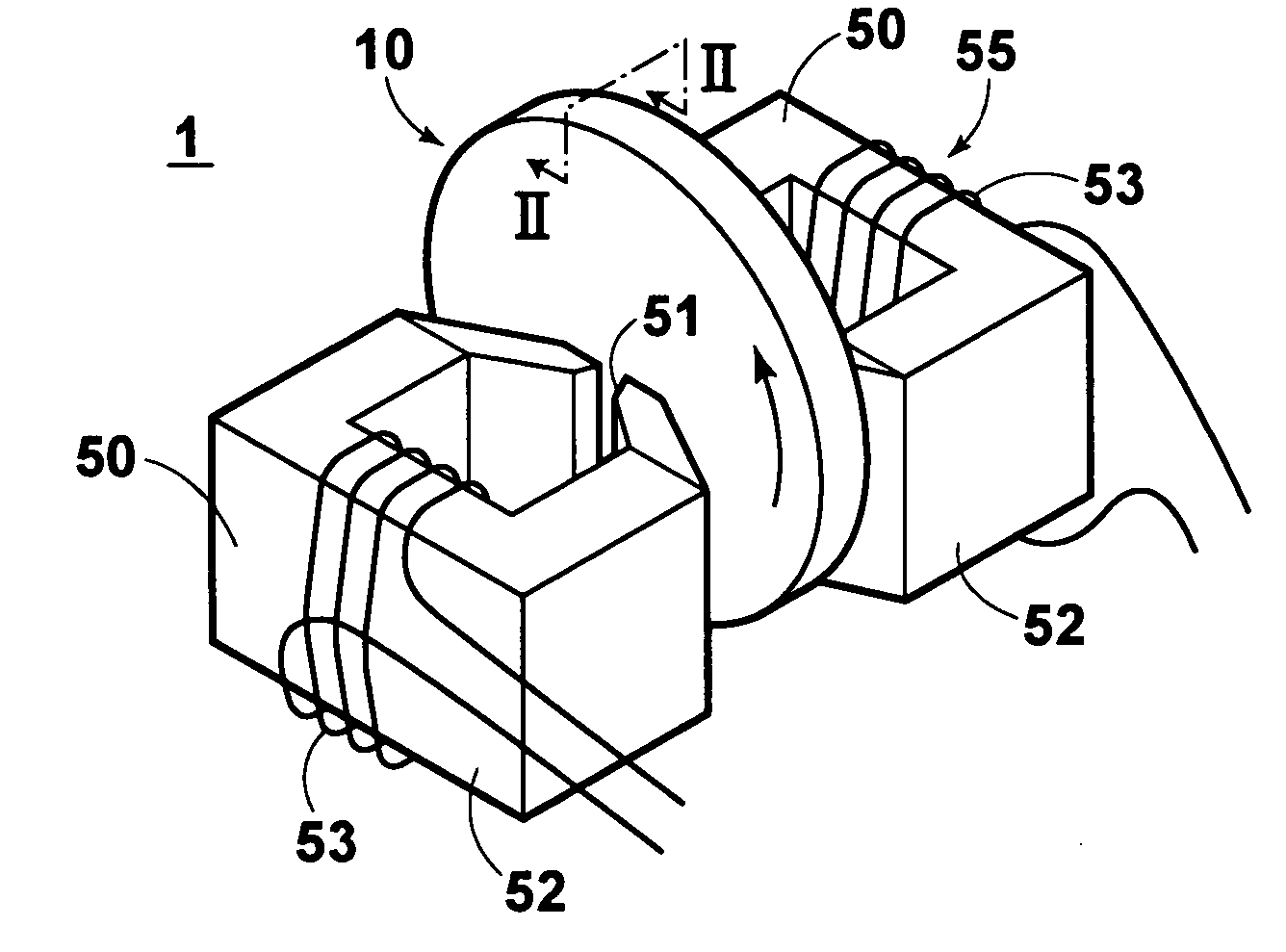
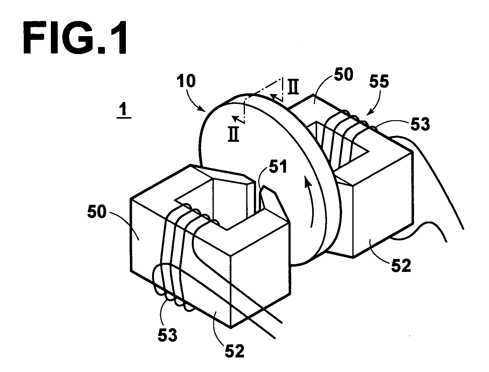
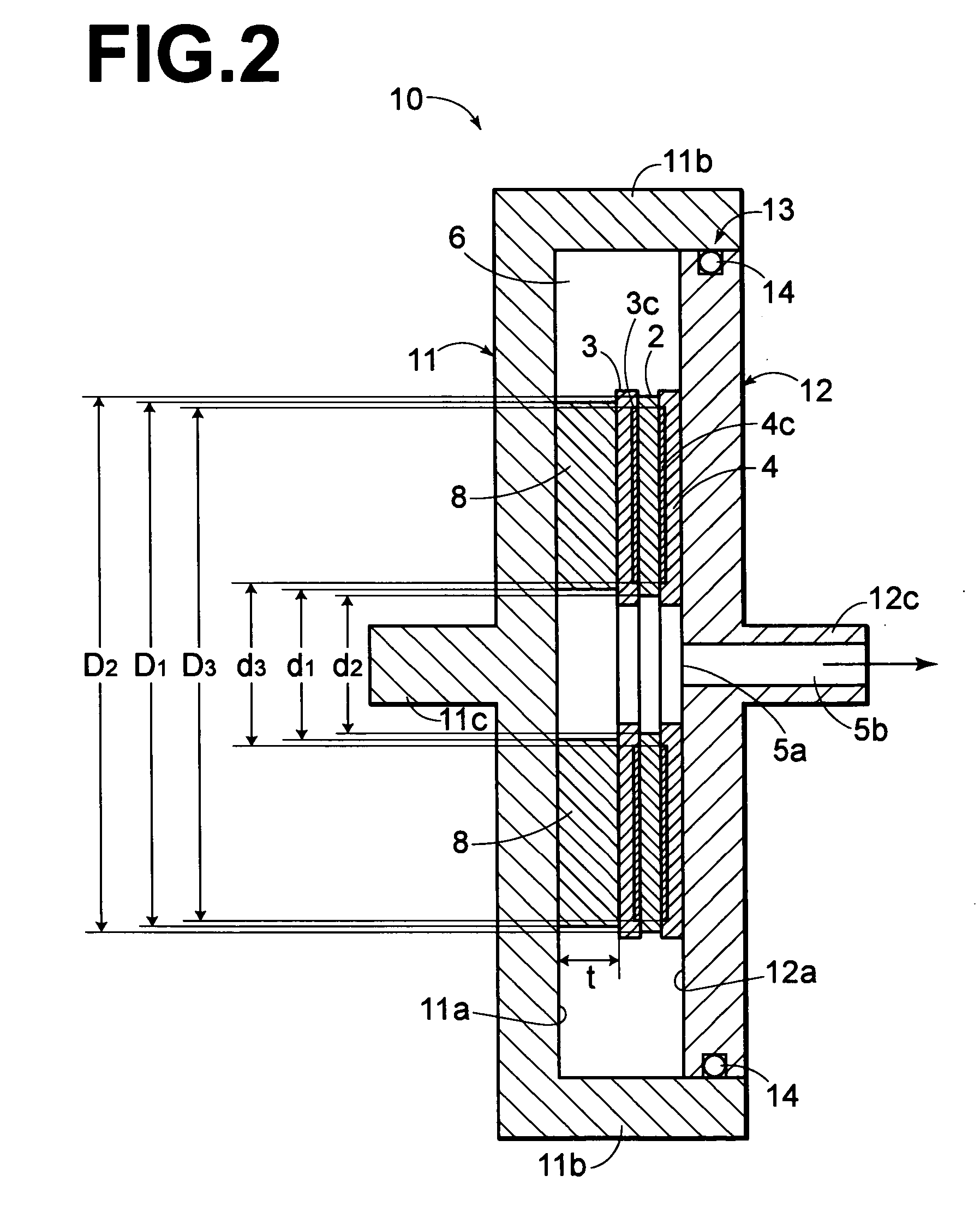
[0031] According to the first magnetic transfer holder of the present invention, the outer diameter D1 of the circular front surface of the elastic body is smaller than the outer diameter D2, which is the smaller one of the outer diameter of the master information carrier and the outer diameter of the slave medium. Therefore, intensive pressurization on the edges of the outer peripheries of the master information carrier and the slave medium is prevented, and no damage is caused to the edges of the outer peripheries of the master information carrier and the slave medium. Further, since the master information carrier and the like do not bite into outer periphery of the elastic body, no damage is caused to the elastic body.
[0032] Further, when the master information carrier and the slave medium, which are sandwiched and held, have center holes, intensive pressurization at the edges of the center holes of the master information carrier and the slave medium, i.e. the edges of the inner peripheries is prevented and no damage is caused to edges of outside peripheries of the master information carrier and the slave medium, on the condition that a circular front surface of the elastic body has a center hole, and a diameter d1 of the center hole is larger than a diameter d2, which is the larger one of a diameter of the center hole of the foregoing master information carrier and a diameter of the center hole of the foregoing slave medium. Further, since the master information carrier and the like do not bite into the inner periphery of the elastic body, no damage is caused to the elastic body.
[0033] Further, when a difference between the outer diameter D1 and the outer diameter D2 and / or a difference between the diameter d1 and the diameter d2 is set between 0.2 mm and 4 mm, inclusive, the elastic body can be arranged so that the elastic body does not protrude from the master information carrier, and a uniform pressure can be applied over the entire contact area of the master information carrier and the slave medium which are superimposed. Therefore, both the master information carrier and the slave medium can be surely contacted over the entire contact area, excellent signal transfer can be performed, and excellent signal quality level can be obtained in the slave medium after transfer.
[0034] Further, when the outer diameter D1 is larger than the outer diameter D3 of the pattern area of the master information carrier, and / or the diameter d1 is smaller than the inner diameter d3 of the pattern area of the master information carrier, a uniform pressure can be applied in the pattern areas of the master information carrier and the slave medium. Therefore, excellent signal transfer can be performed, and excellent signal quality level can be obtained in the slave medium after transfer.
[0037] The magnetic transfer device of the present invention uses the foregoing magnetic transfer holder of the present invention, and performs magnetic transfer in a state in which pressure is applied onto two sides of the foregoing contact body. Therefore, magnetic transfer can be performed while applying uniform pressure over the entire contact area, and excellent signal quality level can be obtained.

Problems solved by technology

In order to improve transfer quality in this magnetic transfer, how uniformly the slave medium and the master information carrier contact each other is an important issue.
When magnetic transfer is not performed, signal drop-outs arise in the magnetic information transferred to the slave medium, and the signal quality level deteriorates.
In this regard, when the recorded signal is a servo signal, a tracking function is not fully obtained and reliability is decreased.
However, there has been a problem that obtaining close contact over the entire contact area is difficult due to a difference of flatness among the master information carrier, the slave medium, and the holder.
However, when magnetic transfer was performed by using a holder tightly holding a contact body comprising the master information carrier and the slave medium via the elastic body, damage or deformation occurred to the edges of the master information carrier and the slave medium.
Further, at portions slightly inward from the outer and inner peripheral edges, some areas receiving low pressure were generated, wherein the signal quality level deteriorated.
Meanwhile, when a difference between the relevant diameters becomes larger than 4 mm, pressure at the edges of the inner and outer diameters becomes low, and signal quality level in the vicinity of the edges may deteriorate.
When the thickness of the elastic body is too thin, the amount of deformation necessary to absorb holder flatness and unevenness in the thicknesses of the master, the slave, and the elastic body cannot be obtained.
In addition, when a degree of elasticity of the elastic body is lower than 0.5 MPa, accurate positioning becomes difficult.
Further, a material having a low elastic modulus such as foamed rubber generally tends to generate dust.
In this case, therefore, dust may be interposed between the master information carrier and the slave medium during contact thereof, causing signal drop-out.
However, respective diameters of the two master carriers are not necessarily identical.
Further, when a elastic modulus is too low, the master information carrier moves due to easy deformation of the elastic body even if the master information carrier is fixed, so that accurate positioning becomes difficult.

Method used


Image

  • Magnetic transfer holder and magnetic transfer device
  • Magnetic transfer holder and magnetic transfer device
  • Magnetic transfer holder and magnetic transfer device

Examples


Embodiment Construction

[0097] A concrete example of the present invention and Comparative examples 1 and 2 will be described.

[0098] In each example, respective magnetic transfer holders comprise the first holder and the second holder of the first embodiment, and tightly hold two sides of a contact body via respective elastic bodies having a thickness of 0.5 mm.

[0099] Master information carriers and slave mediums which are sandwiched and held by the magnetic transfer holders in the Example and comparative examples are identical. The master information carriers, the slave mediums, an elastic body of the Example, an elastic body of Comparative example 1, and an elastic body of Comparative example 2 each have center holes, and their center hole diameters (inner diameters) d and outer diameters D are as shown in Table 1:

1 TABLE 1 Inner diameter d Outer diameter D (mm) (mm) Master 29.0 84.0 information carrier Slave medium 25.0 84.0 Elastic body of 29.1 83.9 Example Elastic body of 29.0 84.0 Comparative example...


PUM

PropertyMeasurementUnit
outer diameter D2aaaaaaaaaa
outer diameter D3aaaaaaaaaa

Abstract

A magnetic transfer holder holds a contact body including superimposed master information carriers bearing transfer information in pattern areas and a slave medium. At least one of the two sides of the contact body is held via an elastic body. A surface of this elastic body that faces the master information carrier is circular. An outer diameter D1 of this elastic body is smaller than an outer diameter D2, which is the smaller one of an outer diameter of the master information carrier and that of the slave medium, and larger than an outer diameter D3 of the pattern area. A diameter d1 of a center hole of the elastic body is larger than an outer diameter d2, which is the larger one of a center hole of the master information carrier and that of the slave medium, and smaller than an inner diameter d3 of the pattern area.

Description

[0001] 1. Field of the Invention[0002] The present invention relates to a magnetic transfer holder which is used in magnetic transfer of information, from a master information carrier that bears the information, to a slave medium, and a magnetic transfer device.[0003] 2. Description of the Related Art[0004] Magnetic transfer is the subject matter of the present invention. The object of magnetic transfer is to transfer and record a magnetization pattern corresponding to information, which is borne by a master information carrier, to a slave medium. This is accomplished by applying a transfer magnetic field in a state in which the master information carrier (patterned master) having a magnetic layer at least on its surface, in which a transfer pattern such as servo signals is formed as an uneven pattern or as embedded structures, contacts the slave medium which has a magnetic recording portion.[0005] When the foregoing slave medium is a discoid medium such as a hard disk or a high-den...

Claims


Application Information

Patent Timeline
Patent Type & Authority Applications(United States)
IPC IPC(8): G11B5/86G11B23/50
CPCG11B23/505G11B5/865D05B23/009
Inventor KAMATANI, AKITO
Owner FUJIFILM CORP
Learn More