
Dental appliance for improving airflow through nasal-pharyngeal airway

a technology of nasal pharyngeal airway and dental appliance, which is applied in dental surgery, snoring prevention, tooth capping, etc., can solve the problems of reducing the resistance of airflow through the pharyngeal region, and achieve the effect of improving airflow for breathing, reducing the resistance of airflow through the pharyngeal region, and maintaining the free flow of air

Active Publication Date: 2004-09-16
ABRAMSON MARK
View PDF13 Cites 39 Cited by
  • Summary
  • Abstract
  • Description
  • Claims
  • Application Information

AI Technical Summary

Benefits of technology

[0011] (a) to provide an improved device for improving air flow through the nasal and pharyngeal air passage, preventing snoring and sleep apnea.
[0014] (d) to provide an anti-snoring device which maintains maximum intraoral tongue space,
[0017] Still further, to provide a device for improved nasal breathing and providing additional protection form traumatic injury which is incorporated into athletic mouth guards.
[0020] In accordance with this invention I provide a device for improving airflow for breathing by stretching the skin of upper lip region and the nose to maintain the free flow of air through the nasal air passage. The device comprises a base element that anteriorly repositions the lower jaw, thus repositioning the base of the tongue anteriorly. This reduces the resistance of airflow through the pharyngeal region by preventing the tongue from falling back during sleep and obstructing the pharyngeal airway located in back of the tongue region.DRAWINGS--FIGURES

Problems solved by technology

This reduces the resistance of airflow through the pharyngeal region by preventing the tongue from falling back during sleep and obstructing the pharyngeal airway located in back of the tongue region.

Method used


Image

  • Dental appliance for improving airflow through nasal-pharyngeal airway
  • Dental appliance for improving airflow through nasal-pharyngeal airway
  • Dental appliance for improving airflow through nasal-pharyngeal airway

Examples


Embodiment Construction

. 1-4

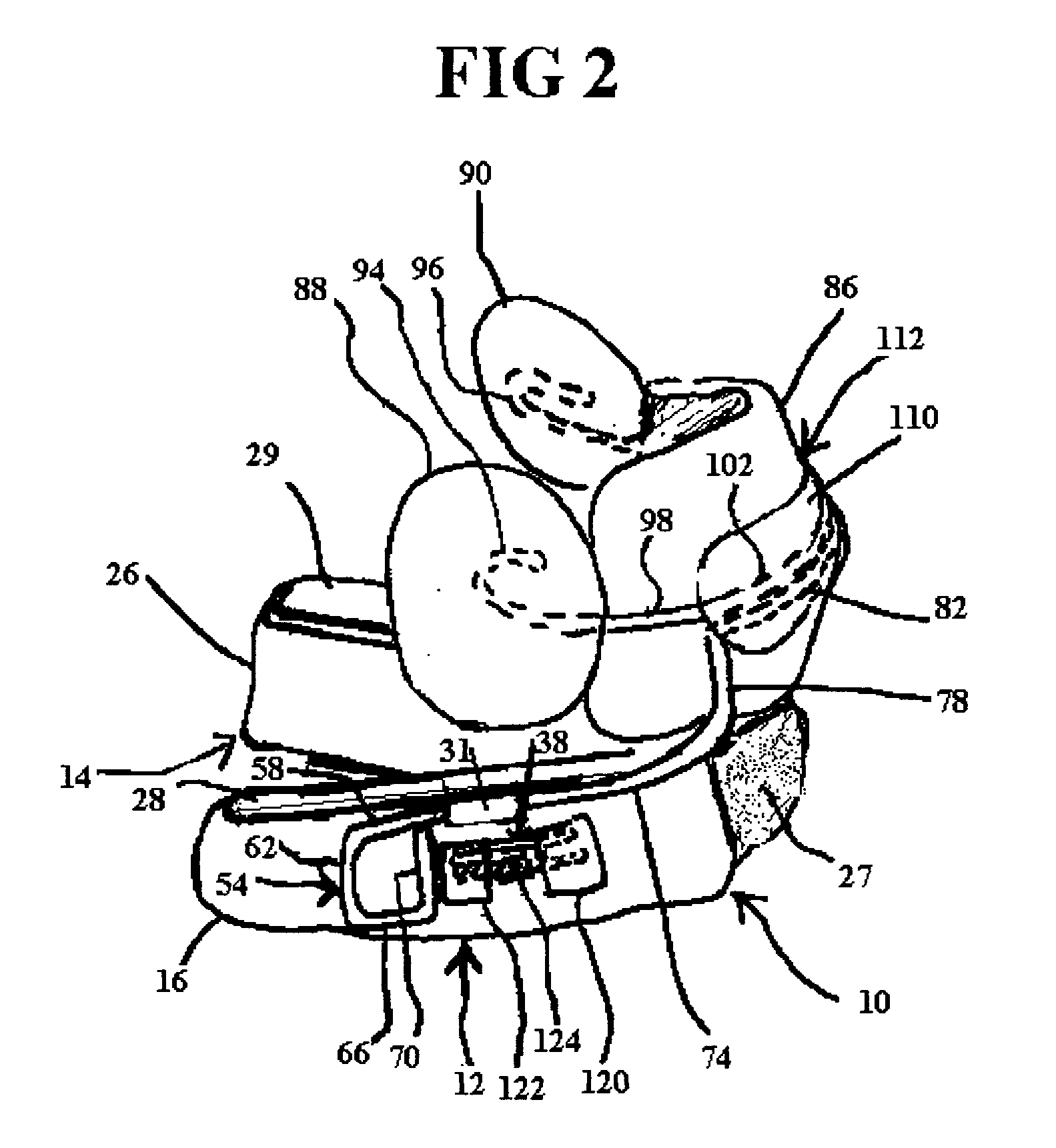
[0051] A preferred embodiment of a nasal dilator and anti-snoring device according to the invention is illustrated and FIG. 1 (anterior view), FIG. 2 (lateral view), FIG. 3 (posterior view), and FIG. 4 (top view). The device has a base unit 10, which fits over the lower teeth. It is constructed of thermoplastic material, which is heat molded over a dental model.backslash. of the patient's teeth. In the preferred embodiment, the thermoplastic material used is 3 mm thick biocryl, available from Great Lakes Orthodontics of Tonawanda, N.Y. The biocryl is pressure molded over the dental casts of the lower teeth using a Biostar thermoplastic molding unit, available through Great Lakes Orthodontics.

[0052] The resultant molded form is cut in the inner side (lingual / tongue) of the dental arch approximately 3-5 mm below the upper margin of the gum line from the back of the posterior-most tooth on the right completely around the dental arch to the posterior-most tooth on the left. The mol...


PUM


Abstract

A dental device comprises an intraoral nasal dilator and a mandibular repositioner working synergistically as an anti-snoring device. The device has a lower segment of thermoplastic material which is formed to fit over the lower teeth and is connected to an upper section of molded material extending between the upper jaw and the upper lip by a wire connector. The wire connector has mechanisms allowing adjustment of the lower jaw positioning. A wire extension with acrylic pads at end is bonded in the midline of the flange and extends out so that the pads stretch the tissue of the lip and lateral nasal walls preventing collapse during respiration while the anterior repositioning of the lower jaw maintains opening of the posterior pharyngeal airway during sleep functioning as an anti-snoring device. Additional applications of the intraoral nasal dilator include incorporation into sports mouth guards using a variety of materials.

Description

BACKGROUND FOR INVENTION--DISCUSSION OF THE PRIOR ART[0001] Upper airway resistance to airflow is an affliction which affects millions of individuals and has very serious medical consequences with significant morbidity and mortality. The health effects are brought about by the disruption of normal sleep of those afflicted with snoring and sleep apnea (complete stoppage of breathing for a period of time). The effects of snoring and sleep apnea may also compromise the well being of those sleeping in proximity to the afflicted person by disrupting their ability to achieve healthy, restful sleep.[0002] Sleep is impacted by both the increased effort needed to overcome increased resistance to airflow and by the fragmentation of sleep patterns brought about by awakenings that occur in both hyponia (reduced air flow) and apneic events (periods of stoppage of air flow). These conditions limit one's ability to go into the deeper stages of sleep that are necessary to refresh and restore and ar...

Claims


Application Information

Patent Timeline
IPC IPC(8): A61F5/56
CPCA61F5/566
Inventor ABRAMSON, MARK
Owner ABRAMSON MARK
Learn More